External charging coil assembly for charging a medical device

a technology of external charging coil and medical device, which is applied in the direction of exchanging data chargers, transportation and packaging, and delivering patients, etc., can solve the problems of patient safety risks and detract from the efficiency of power transfer

Active Publication Date: 2018-03-27
BOSTON SCI NEUROMODULATION CORP
View PDF50 Cites 22 Cited by
  • Summary
  • Abstract
  • Description
  • Claims
  • Application Information

AI Technical Summary

Problems solved by technology

Such Eddy currents may generate heat unwanted heat, providing a patient safety risk, and will also generally detract from the efficiency of power transfer by sinking some of the energy in the magnetic charging field 65.

Method used


Image

  • External charging coil assembly for charging a medical device
  • External charging coil assembly for charging a medical device
  • External charging coil assembly for charging a medical device

Examples


Embodiment Construction

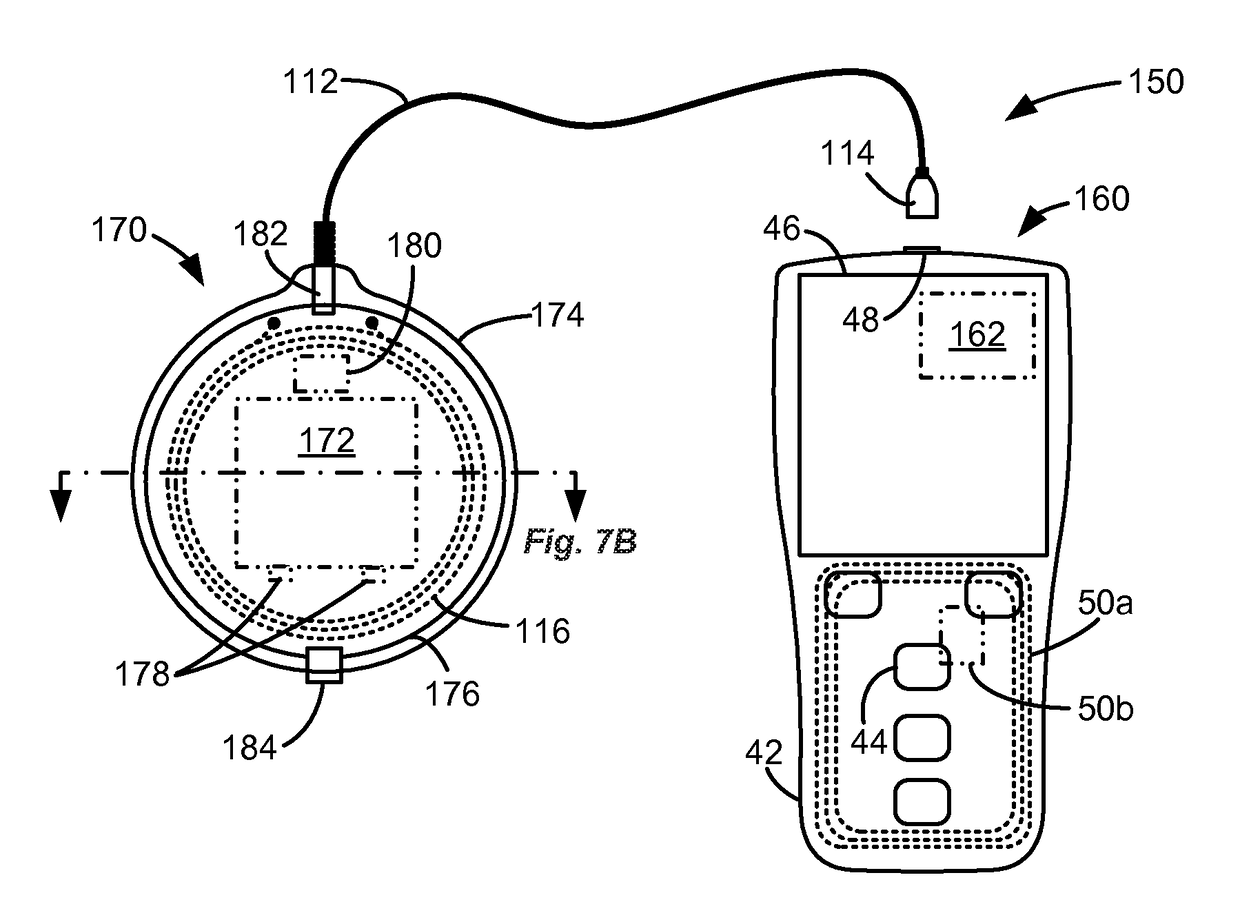
[0041]The inventors see value in the integrated external controller / charger system 90 as disclosed in U.S. Pat. No. 8,498,716 and as depicted here in FIGS. 5A and 5B. However, the inventors also see shortcomings with this approach, particularly as concern system power. Although the '716 patent doesn't disclose the internal circuitry of its integrated external controller / charger 100, the inventors would configure such circuitry as shown here in FIG. 6. In FIG. 6, the external controller / charger 100 is depicted as having a magnetic induction coil antenna 50a for telemetry with the IMD 10 as taught in the '716 patent, although the inventors recognize that an RF antenna 50b (FIG. 3) could also be used depending on the antenna 28 used in the IMD 10 and the particulars of wireless data link 45.

[0042]As shown, the external controller / charger 100 includes control circuitry, such as a microcontroller 130. The microcontroller 130 can control the reception (RX) of data from the IMD 10 (e.g., s...


PUM


Abstract

An integrated external controller / charger system for an implantable medical device is disclosed comprising an external controller / charger device with a Graphical User Interface (GUI) and first battery, and an external charging coil assembly coupleable to the external controller / charger device and including or associated with a second battery. The second battery is used to energize a charging coil in the external charging coil assembly, while the first battery is used to power other aspects of the system (data telemetry circuitry, control circuitry, the GUI, etc.). Because the second battery powers the relatively high-power charging function, the first battery in the external controller / charger device can be made smaller. Additionally, the second battery enables a suitable external controller device (e.g. a mobile device such as a cell phone) to provide charging functionality even if its first battery is otherwise inadequate.

Description

CROSS REFERENCE TO RELATED APPLICATIONS[0001]This application is a non-provisional of U.S. Provisional Patent Application Ser. No. 62 / 072,737, filed Oct. 30, 2014, which is incorporated by reference in its entirety, and to which priority is claimed.FIELD OF THE INVENTION[0002]The present invention relates to a data telemetry and power transfer system having particular applicability to implantable medical device systems.BACKGROUND[0003]Implantable stimulation devices deliver electrical stimuli to nerves and tissues for the therapy of various biological disorders, such as pacemakers to treat cardiac arrhythmia, defibrillators to treat cardiac fibrillation, cochlear stimulators to treat deafness, retinal stimulators to treat blindness, muscle stimulators to produce coordinated limb movement, spinal cord stimulators to treat chronic pain, cortical and deep brain stimulators (DBS) to treat motor and psychological disorders, and other neural stimulators to treat urinary incontinence, slee...

Claims


Application Information

Patent Timeline
Patent Type & Authority Patents(United States)
IPC IPC(8): H02J50/80H02J50/12H02J7/02H02J5/00H04B5/00A61N1/372A61N1/378H02J7/00
CPCH02J7/025A61N1/3787A61N1/37229H02J5/005H02J7/0042H02J7/0054H02J50/12H02J50/80H04B5/0037H02J7/0047H04B5/0081H02J2007/0096H02J7/342H02J7/00034H02J2310/23
Inventor AGHASSIAN, DANIELLEWIS, TERRIL G.
Owner BOSTON SCI NEUROMODULATION CORP
Why Eureka
Try Eureka