
Vehicle Rearview Assembly Including a Display for Displaying Video Captured by a Camera and User Instructions

a rearview assembly and video camera technology, applied in the field of vehicle rearview assemblies including high intensity displays, can solve the problems of not being able to provide a large lcd the driver typically looks in the rearview mirror while backing up, and it is difficult to look at both the rearview mirror and the display in the instrument panel at the same tim

Inactive Publication Date: 2009-04-16
GENTEX CORP
View PDF40 Cites 491 Cited by
  • Summary
  • Abstract
  • Description
  • Claims
  • Application Information

AI Technical Summary

Problems solved by technology

There, it is not practical or economical to provide a large LCD display in the instrument panel that is solely used for the purpose of a back-up display.
Another problem associated with placing a back-up assist display in the instrument panel is that a driver typically looks in the rearview mirror while backing up and not at the instrument panel.
In any event, it is difficult to look at both the rearview mirror and the display in the instrument panel at the same time.
Although it has been proposed to incorporate such video displays in a rearview mirror assembly, such proposals have not been adopted by the auto industry for several reasons.
However, this leaves a large area of the mirror surface without a reflective layer such that when the mirror element is being used in the conventional sense, it appears much smaller to the driver.
While this latter proposal is very advantageous in that the mirror appears as a normal mirror when the display is not utilized, a difficulty arises insofar as commercially available automotive grade LCD displays are not bright enough to provide a sufficiently bright image to the driver of the vehicle.
A further problem results in that the transflective layer reflects a high percentage of the ambient light striking the mirror from the rear of the vehicle, and such reflected ambient light tends to wash out the image from the LCD display.
This results in the display not having a sufficient contrast ratio for the driver to pick out possible obstructions to the rear of the vehicle.
This is unacceptable given the additional problem of the decreased contrast ratio resulting from providing a mirrored surfaced in front of the LCD display.

Method used


Image

  • Vehicle Rearview Assembly Including a Display for Displaying Video Captured by a Camera and User Instructions
  • Vehicle Rearview Assembly Including a Display for Displaying Video Captured by a Camera and User Instructions
  • Vehicle Rearview Assembly Including a Display for Displaying Video Captured by a Camera and User Instructions

Examples


Embodiment Construction

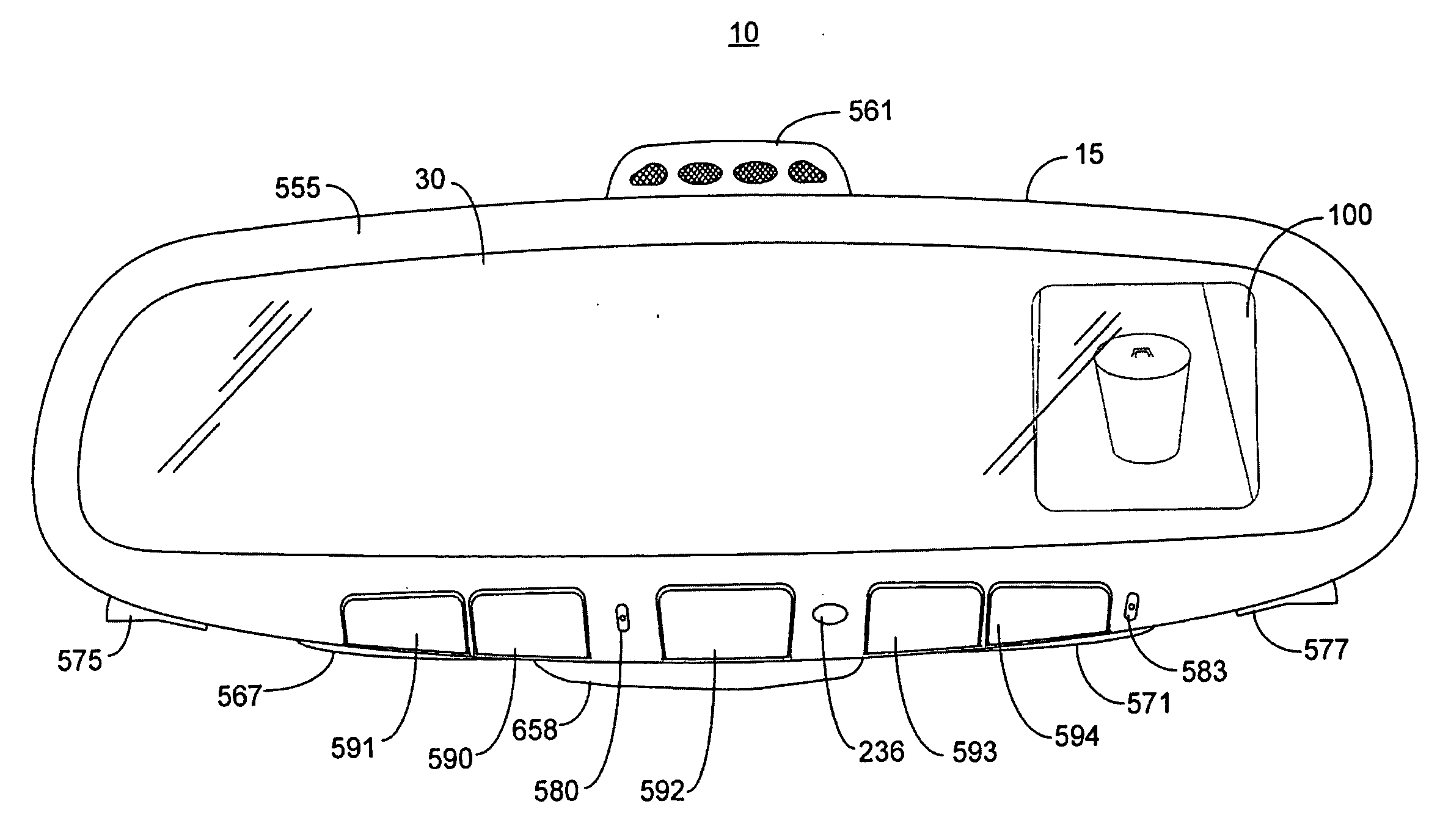
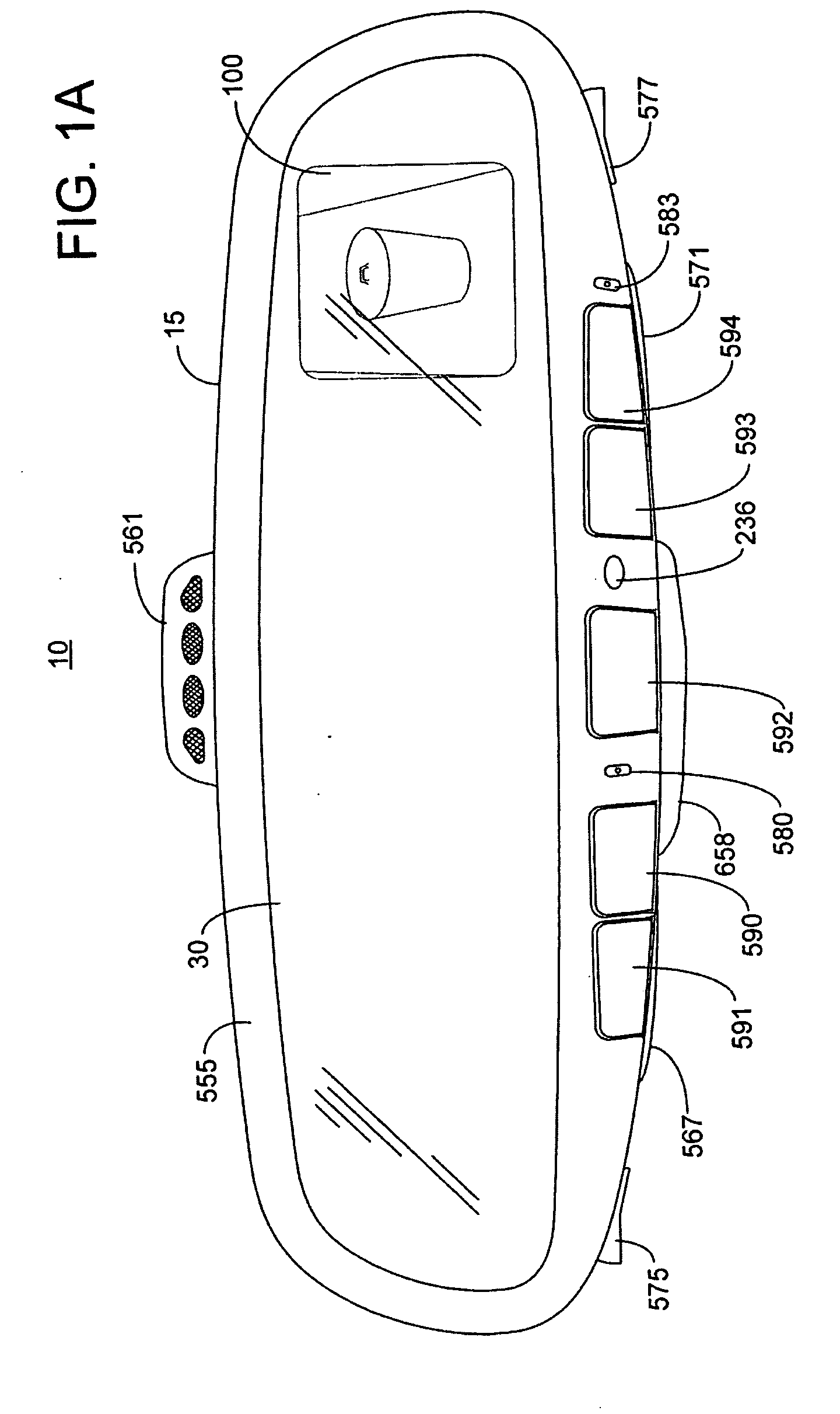
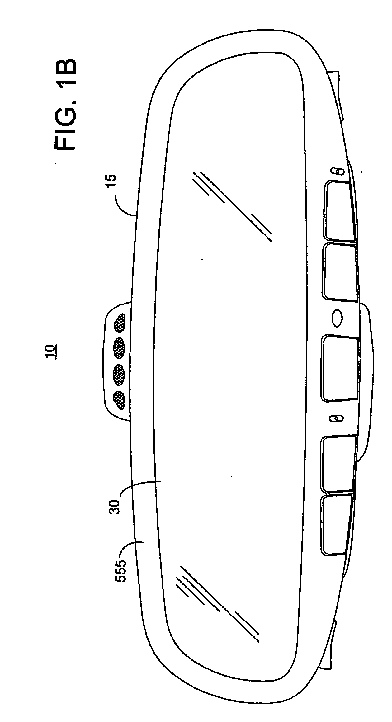
[0089]Reference will now be made in detail to the presently preferred embodiments of the invention, examples of which are illustrated in the accompanying drawings. Wherever possible, the same reference numerals will be used throughout the drawings to refer to the same or like parts.

[0090]For purposes of description herein, the terms “upper,”“lower,”“right,”“left,”“rear,”“front,”“vertical,”“horizontal,”“top,”“bottom,” and derivatives thereof shall relate to the invention as shown in the drawings. However, it is to be understood that the invention may assume various alternative orientations, except where expressly specified to the contrary. It is also to be understood that the specific devices illustrated in the attached drawings and described in the following specification are simply exemplary embodiments of the inventive concepts defined in the appended claims. Hence, specific dimensions, proportions, and other physical characteristics relating to the embodiment disclosed herein are...


PUM


Abstract

An inventive rearview assembly (10) for a vehicle may comprise a mirror element (30) and a display (100) including a light management subassembly (101b). The subassembly may comprise an LCD placed behind a transflective layer of the mirror element. Despite a low transmittance through the transflective layer, the inventive display is capable of generating a viewable display image having an intensity of at least 250 cd / m2 and up to 6000 cd / m2. The rearview assembly may further comprise a trainable transmitter (910) and a graphical user interface (920) that includes at least one user actuated switch (902, 904, 906). The graphical user interface generates instructions for operation of the trainable transmitter. The video display selectively displays video images captured by a camera and the instructions supplied from the graphical user interface.

Description

CROSS-REFERENCE TO RELATED APPLICATIONS[0001]This application claims the priority benefit of U.S. Provisional Application No. 60 / 956,263 filed on Aug. 16, 2007, the entire disclosure of which is incorporated herein by reference.BACKGROUND OF THE INVENTION[0002]The present invention generally relates to vehicle rearview assemblies and vehicle displays. More particularly, the present invention relates to vehicle rearview assemblies including a high intensity display.[0003]One vehicle accessory that has recently become popular is a back-up assist display which provides a video image to the driver of a scene to the rear of the vehicle where the driver's view may otherwise be obstructed. Sport utility vehicles and trucks have larger areas that are obstructed, and thus particularly benefit from this feature. This feature is a significant safety feature insofar as it helps to eliminate the possibility that someone may back up over a child or pet playing behind the vehicle or otherwise back...

Claims


Application Information

Patent Timeline
Patent Type & Authority Applications(United States)
IPC IPC(8): H04N5/00G05B19/00
CPCB60R1/12H04N7/183B60R2001/1253B60R2001/1215
Inventor BAUER, FREDERICK T.VANVUUREN, MARK A.
Owner GENTEX CORP
Learn More