Steaming device

a technology of steaming device and steaming chamber, which is applied in the direction of lighting and heating apparatus, conditioning apparatus, and materials and paper. it can solve the problems of increased water levels not being evaporated, insufficient contact with the heated surface design, and insufficient time for water

Active Publication Date: 2018-03-27
VERSUNI HLDG BV
View PDF19 Cites 0 Cited by
  • Summary
  • Abstract
  • Description
  • Claims
  • Application Information

AI Technical Summary

Benefits of technology

[0008]With this arrangement, the steaming device can produce sufficient steam irrespective of its orientation without water spill-out, irregular or inadequate steam generation.
[0012]Thus, the flow rate is configured to decrease as the heated surface moves from a horizontal to an inclined position. This allows for sufficient time for water to spread across the heated surface to evaporate and for the heated surface to heat up again ready for next dose of water
[0015]This enables the tolerance H to be minimised. H is the tolerance of the fluid impact on the heated surface as the steaming device is moved from an ironing position to an inclined or vertical position. In particular, a high velocity of water enables the amount of contact of dosed water with the heated surface to be maximised even when the direction of water is affected by gravity such that unevaporated water does not collect in parts of the steaming device causing excessive cooling of said parts and leaving areas of the heated surface and / or other parts to overheat.
[0021]This enables the velocity of the fluid exiting the fluid inlet in a direction towards the heated surface to be changed.
[0024]This enables fluid to impact the heated surface within a predetermined region, thereby reducing unevaporated water accumulating in the steaming device.
[0027]This method enables the steaming device to generate sufficient steam irrespective of its orientation without water spill-out, irregular or too little steam generation.

Problems solved by technology

Additionally, after impact, due to gravity, water does not spread across the heated surface in the same way as when the steaming device is in its ironing position and so it does not get sufficient time in contact with the heated surface designed for the spreading of such large amounts of water in the normal ironing position.
This may result in insufficient time for water to spread across the heated surface, or inadequate spreading of water across the heated surface, prior to the next dose of water leading to increased levels of water not being evaporated.
As a result water may accumulate at the bottom of the steam generator resulting in excessive water spitting out from the device when the device is orientated back to its ironing position or is kept in an inclined position for too long.

Method used


Image

  • Steaming device
  • Steaming device
  • Steaming device

Examples


Embodiment Construction

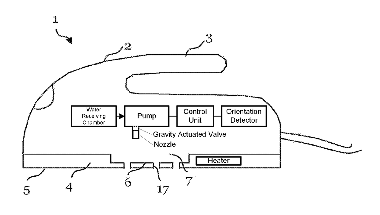
[0033]An embodiment of the present invention relates to a steam iron 1 acting as a steaming device as shown in FIG. 1. Such a steam iron 1 is generally used to apply steam to a fabric of a garment to remove creases from the fabric. Although the embodiments described below will relate to applying steam to the fabric of a garment, it will be appreciated that such a steam iron may be used to remove creases from other fabrics and materials. Furthermore, although in the embodiments described below the steaming device is a steam iron, it will be understood that the invention is not limited thereto and that the invention may relate to other types of steaming devices, such as a hand-held steamer or the like. Such alternative steaming devices can be used for applying steam for treating curtains and soft surfaces of upholstery such as textile coverings of furniture and mattresses.

[0034]Referring now to FIG. 1, the steam iron 1 comprises a housing 2 and a handle 3. The handle 3 is integrally f...


PUM


Abstract

The present application relates to a steaming device. The steaming device comprises a steam generator (8) having a heated surface (6), a pump configured to direct fluid against the heated surface (6) to generate steam, an orientation detector to detect orientation of the heated surface (6), and a control unit. The control unit is configured to operate the pump to adjust the flow rate of the pump in dependence on the orientation of the heated surface determined by the orientation detector.

Description

[0001]This application is the U.S. National Phase application under 35 U.S.C. § 371 of International Application No. PCT / EP2014 / 064671, filed on Jul. 9, 2014, which claims the benefit of International Application No. 13175771.8 filed on Jul. 9, 2013. These applications are hereby incorporated by reference herein.FIELD OF THE INVENTION[0002]The present application relates to a steaming device. In particular, the present application relates to a steam iron or a steamer, and a method of operating a steaming device.BACKGROUND OF THE INVENTION[0003]Steaming devices, such as steam irons or hand-held steamers are used to remove creases from fabric, such as clothes and bedding. Such a steam iron or hand-held steamer generally comprises a main body with a handle which is held by a user, and has a sole plate with a planar ironing surface which is pressed or located against the fabric of a garment. A steam generator is disposed in the main body, so that water fed from a water receiving chamber...

Claims


Application Information

Patent Timeline
Patent Type & Authority Patents(United States)
IPC IPC(8): D06F75/18F22B1/28D06F75/26D06F87/00
CPCD06F75/18D06F75/26F22B1/285F22B1/28D06F87/00
Inventor WADHWA, SAHIL A.KRISHNAN VALIYAMBATH, MOHANKUMARONG, CHEE KEONGYIP, KIN LEONG
Owner VERSUNI HLDG BV
Why Eureka
Try Eureka