Sofc system and method of operating a sofc system

Active Publication Date: 2017-11-16
HTCERAMIX
View PDF0 Cites 4 Cited by
  • Summary
  • Abstract
  • Description
  • Claims
  • Application Information

AI Technical Summary

Benefits of technology

The present invention provides a more robust and economically advantageous Solid Oxide Fuel Cell (SOFC) system. The system has a simplified control and requires a smaller condensing heat exchanger. The anode exhaust stream and cathode depleted air stream are kept separate, which reduces the flow of the anode exhaust stream and the burner exhaust stream. This eliminates the need for an external water line and allows for sufficient steam generation without excessive air. The system also has improved control of the burner and better condensation of water, resulting in improved steam generation. Additionally, the system has a higher dew point, which ensures sufficient condensation regardless of changes in the cathode flow rate. This prevents a reduction in the amount of water condensed and ensures continued efficient operation of the system.

Problems solved by technology

One disadvantage of this fuel cell power plant is that the control of the combustion in the burner is difficult in view that having a depleted air coming out of the stack at very high flow rate makes the controllability of a complete combustion, which means a combustion that burns all fuel, challenging, especially when the system operates under modulating loads.
A further disadvantage is that a relatively large burner is necessary in the system.
A further disadvantage is that an external water line and an apparatus for generating steam is necessary to run the system.

Method used


Image

  • Sofc system and method of operating a sofc system
  • Sofc system and method of operating a sofc system
  • Sofc system and method of operating a sofc system

Examples


Embodiment Construction

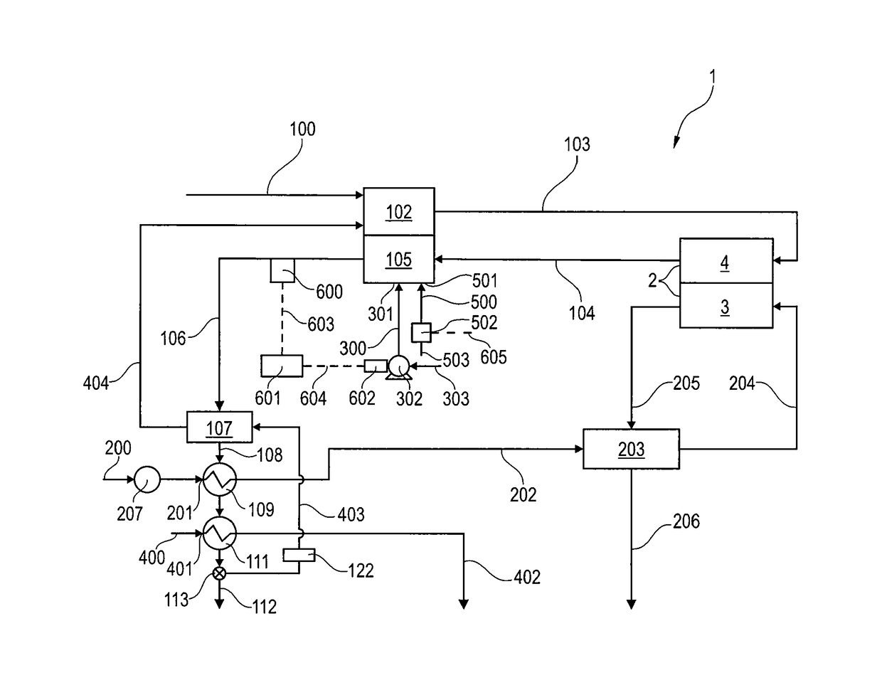
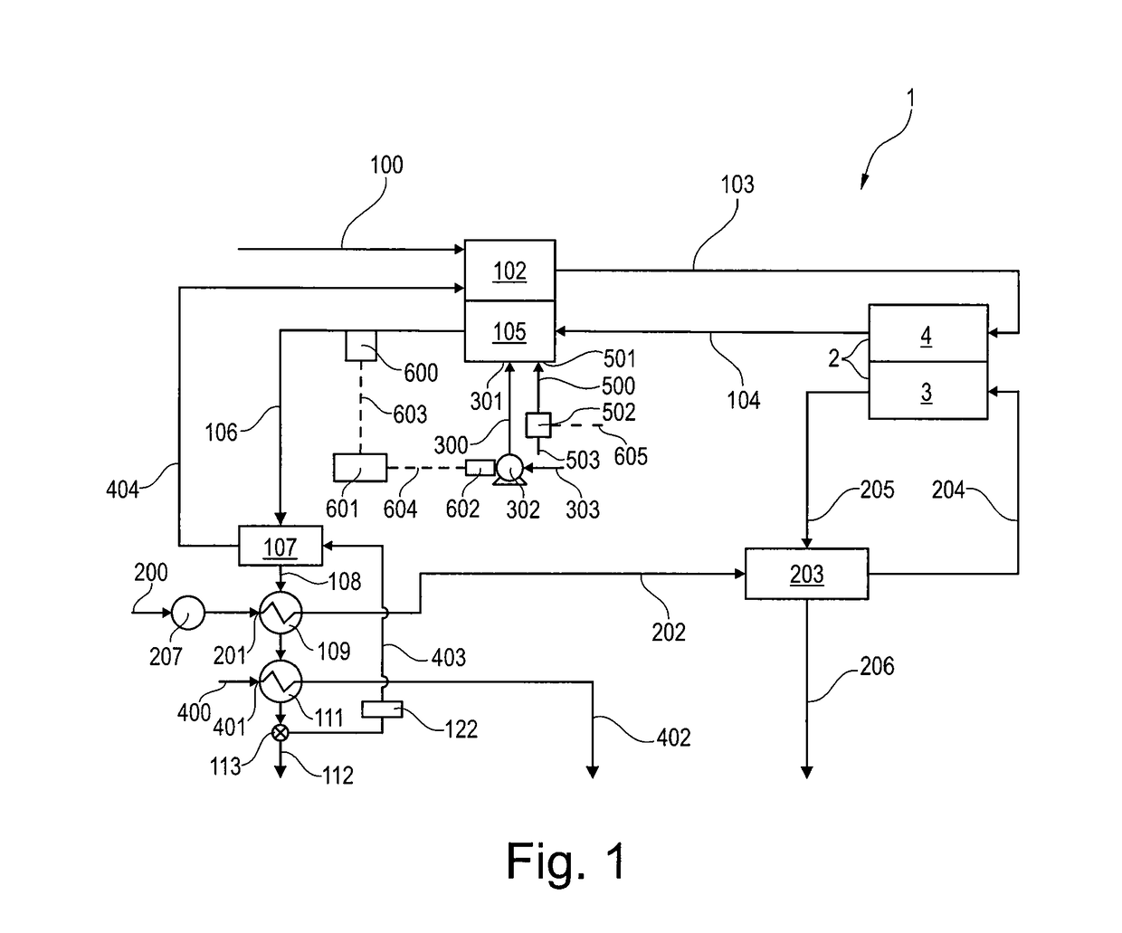
[0036]FIG. 1 is a schematic diagram of a first embodiment of a SOFC system 1 according to the invention. A gaseous hydrocarbon stream 100 and a stream of steam 404 is fed into a reformer 102, wherein the gaseous hydrocarbon stream 100 and steam is converted into reformate fuel containing hydrogen and carbon monoxide gases to produce a hydrogen rich gas. A stream of hydrogen rich gas 103 is directed from the reformer 102 to an anode 4 of a solid oxide fuel cell stack 2. A stream of preheated cathode air 204, provided by a first air blower 207, is directed to a cathode 3 of the solid oxide fuel cell stack 2. The hydrogen of the hydrogen rich gas 103 is oxidized in the solid oxide fuel cell stack 2 to produce electricity, a hydrogen depleted anode exhaust stream 104, which exits the anode 4 of the fuel cell 2, and an oxygen depleted cathode exhaust stream 205, which exits the cathode 3 of the fuel cell 2. The anode exhaust stream 104 and the cathode exhaust stream 205 are not mixed but...


PUM


Abstract

A SOFC system having a fuel reformer for reforming a gaseous hydrocarbon stream and steam into a hydrogen rich gas, a solid oxide fuel cell stack including an anode and a cathode for electrochemically reacting the hydrogen rich gas and a cathode air stream to produce electricity, an anode exhaust stream and a cathode depleted air stream. The anode exhaust stream and the cathode depleted air stream are kept separate, a burner for combusting a mixture of the anode exhaust stream and a fresh air stream to complete combustion and produce heat for the reformer control unit and a blower are also provided. The control unit controlling the blower for controlling the mass flow rate of the fresh air stream to provide heat to the reformer to reform the gaseous hydrocarbon stream and to produce a burner exhaust stream.

Description

FIELD OF THE INVENTION[0001]The field of invention relates to a Solid Oxide Fuel Cell (SOFC) system. The field of invention further relates of a method of operating a Solid Oxide Fuel Cell system.BACKGROUND OF THE INVENTION[0002]A Solid Oxide Fuel Cell (SOFC) is a device for directly converting the chemical energy of a fuel into electrical energy. Document U.S. Pat. No. 4,943,493 discloses a fuel cell power plant, wherein a hydrocarbon fuel is reformed in a reformer to provide a hydrogen rich fuel stream and the hydrogen rich fuel stream is oxidized in a fuel cell. A stream of anode exhaust and an oxidant stream comprising cathode exhaust and air are combusted in the burner. The fuel cell power plant allows indirect control of the burner flame temperature in that the composition of the oxidant stream are controlled to maintain the oxygen content of the burner exhaust stream within a predetermined range and thus maintain the flame temperature of the combustion mixture within a prefer...

Claims


Application Information

Patent Timeline
IPC IPC(8): H01M8/0612C01B3/38H01M8/04701H01M8/04746H01M8/04014H01M8/0432H01M8/124
CPCH01M8/0618H01M8/04022H01M8/04776H01M8/04328H01M8/04738C01B3/38H01M2008/1293C01B2203/0233C01B2203/0827C01B2203/1695C01B2203/066C01B3/48C01B2203/0283C01B2203/0894C01B2203/1294C01B2203/16H01M8/04089H01M8/04164H01M8/04201H01M8/04291H01M8/04373H01M8/0444H01M8/04268Y02E60/50Y02P20/129H01M8/04014H01M8/04082H01M8/04701H01M8/0612
Inventor MATIAN, MARDITBUCHELI, OLIVIER
Owner HTCERAMIX
Why Eureka
Try Eureka