
Steam iron

a steam iron and ironing technology, applied in the field of steam irons, can solve the problems that wrinkles in clothes cannot be effectively removed, and achieve the effect of effectively removing wrinkles in clothes, without increasing the amount of steam

Inactive Publication Date: 2006-06-22
PANASONIC CORP
View PDF9 Cites 4 Cited by
  • Summary
  • Abstract
  • Description
  • Claims
  • Application Information

AI Technical Summary

Benefits of technology

The present invention provides a steam iron that can effectively remove wrinkles in clothes without increasing the amount of steam. The steam iron includes a base with a vaporization chamber, a water tank, and a soleplate with steam holes and depressions. The steam holes are arranged in a line and the depressions are arranged in multiple lines along the steam holes. This design allows for efficient and effective steaming of clothes.

Problems solved by technology

However, the conventional configuration has a drawback in that wrinkles in clothes cannot be effectively removed when clothes are not sufficiently steamed with the ejected steam.

Method used


Image

  • Steam iron
  • Steam iron
  • Steam iron

Examples


first preferred embodiment

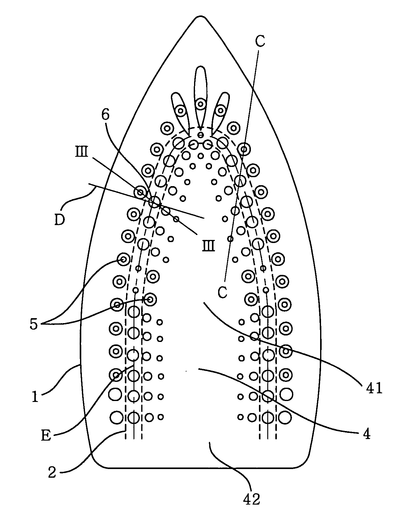
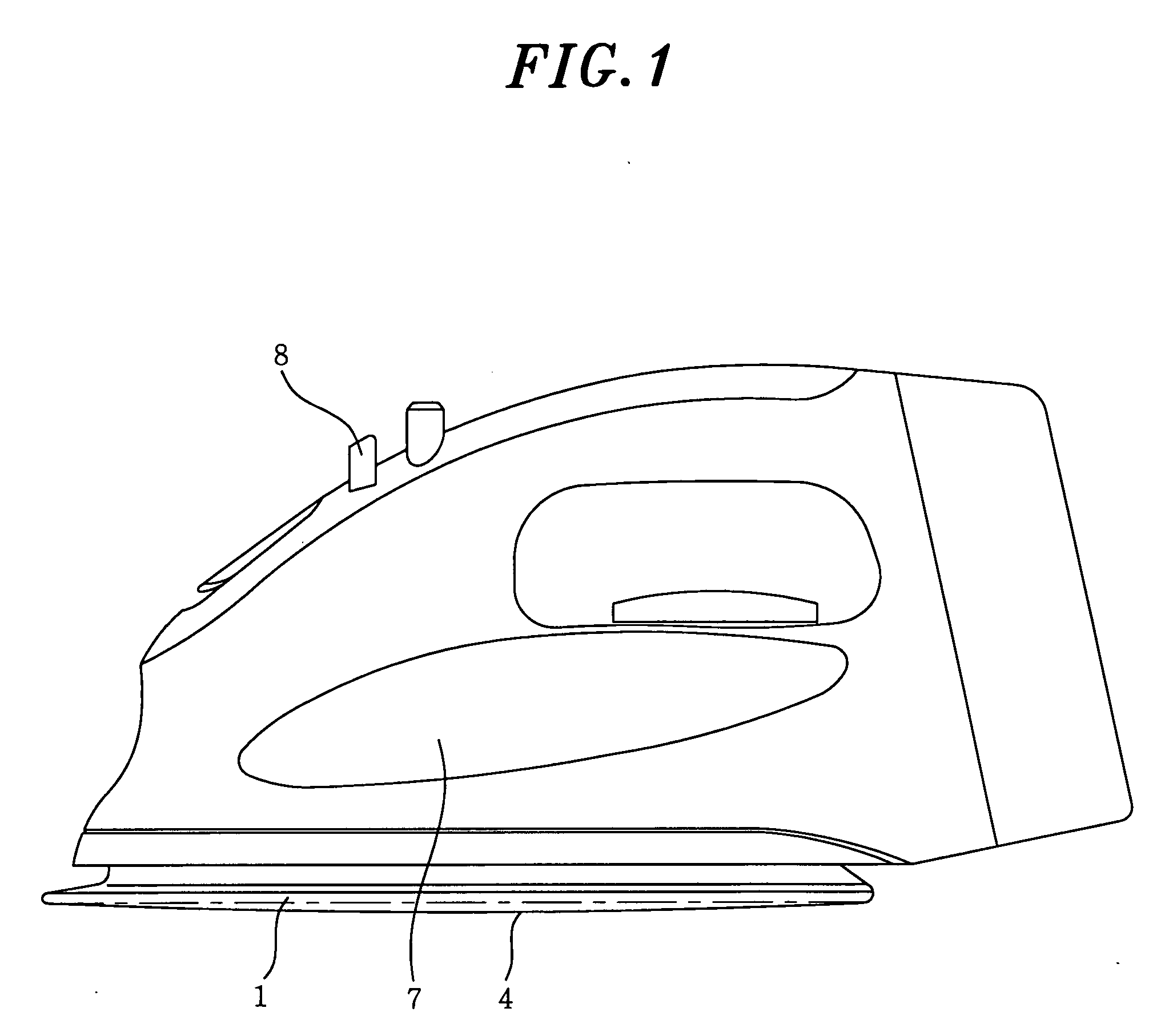
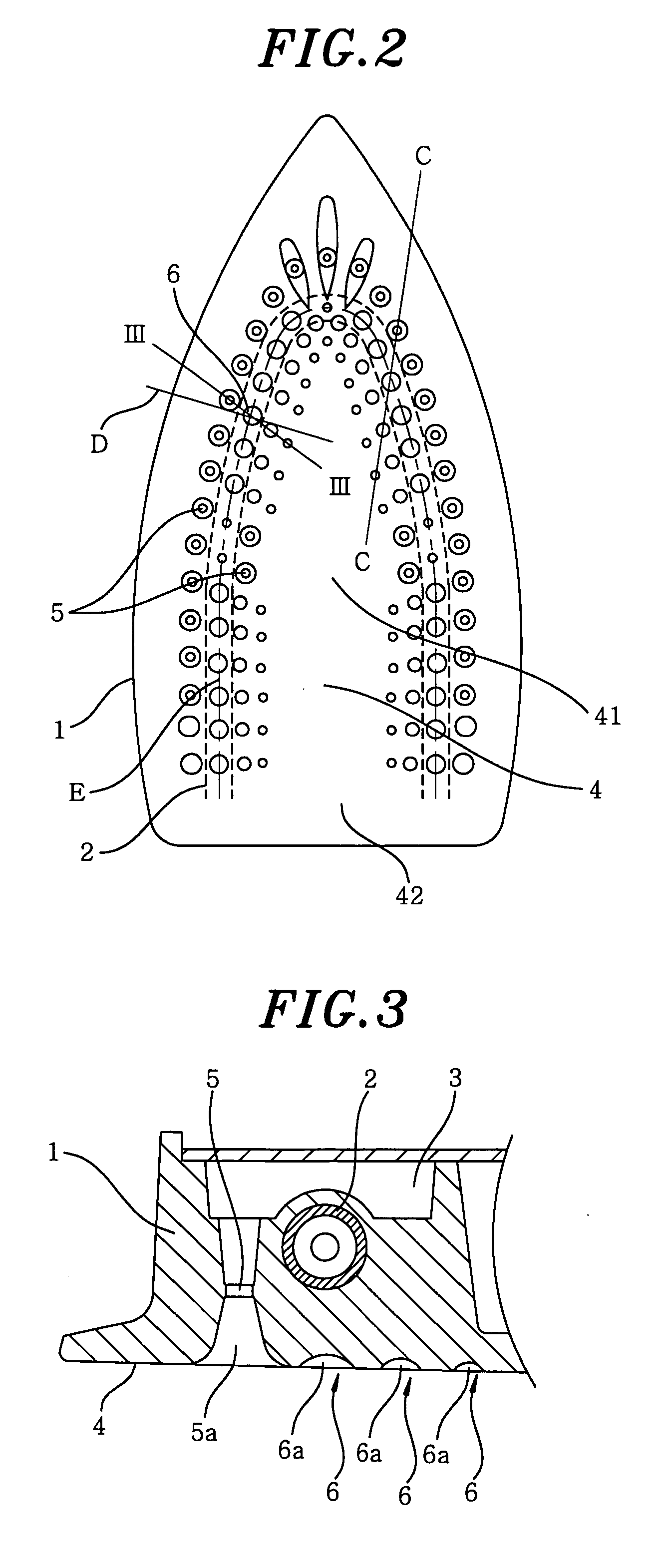
[0013]FIG. 1 shows a side view of a steam iron in accordance with a first preferred embodiment of the present invention; FIG. 2 describes a plan view of a soleplate of a base of the steam iron; FIG. 3 provides a cross sectional view of the base of the steam iron in accordance with the first preferred embodiment, which is taken along line III-III of FIG. 2; FIG. 4 represents a plan view of a soleplate of a base of a steam iron in accordance with a second preferred embodiment of the present invention; and FIG. 5 offers a cross sectional view of the base of the steam iron in accordance with the second preferred embodiment, which is taken along line V-V of FIG. 4.

[0014] Referring to FIGS. 1 to 3, reference numeral 1 is a base heated by heater 2. Vaporization chamber 3 for generating steam is installed at an inner upper portion of the steam iron. As indicated by a dashed line in FIG. 2, approximately U-shaped heater 2 for heating base 1 to a temperature suitable for ironing is buried in...

second preferred embodiment

[0035] Hereinafter, a second preferred embodiment of the present invention will be described with reference to FIGS. 4 and 5. Depressions 60 become narrower and shallower, as their distances from steam holes 50 increase. Further, as indicated by line V-V of FIG. 4, each of steam holes 50 provided at outer side of depressions 60 is arranged such that it is positioned on a longitudinal center line of corresponding one of depressions 60. Other configurations are identical to those of the first preferred embodiment.

[0036] The steam ejected through steam holes 50 is filled in spaces 50a inside steam holes 50 and in spaces 60a inside depressions 60 arranged along steam holes 5. Thus, clothes can be continuously steamed and, then, fibers of the clothes can be sufficiently swelled before soleplate 40 passes therethrough. Further, since depressions 60 are getting narrower and shallower as their distances from steam holes 50 increase, respective amounts of steam in depressions 60 are gradual...


PUM


Abstract

A steam iron includes a base provided with a vaporization chamber for generating steam, the vaporization chamber being heated by a heater; a water tank for storing therein water to be supplied to the vaporization chamber; and a soleplate having a plurality of steam holes and a multiplicity of depressions, the soleplate being provided on a bottom surface of the base and the steam holes being communicated with the vaporization chamber. At least a part of the steam holes is consecutively arranged in a line and, further, at least a part of the depressions is arranged in multiple lines along the steam holes consecutively arranged in the line.

Description

FIELD OF THE INVENTION [0001] The present invention relates to a steam iron for removing wrinkles in clothes or the like. BACKGROUND OF THE INVENTION [0002] Conventionally, such steam iron has a plurality of steam holes arranged in a line along an approximately U-shaped area on its soleplate (see, e.g., Japanese Utility Model Publication No. S48-28073). [0003] The following is a mechanism of removing wrinkles by ironing clothes. Fibers of clothes are swelled by heat and moisture of steam ejected through the steam holes on the soleplate. Accordingly, transformed portions of the fibers, i.e., wrinkles in the clothes, are softened and then immediately dried along a plane of the soleplate by heat and surface pressure thereof, thereby removing the wrinkles. However, the conventional configuration has a drawback in that wrinkles in clothes cannot be effectively removed when clothes are not sufficiently steamed with the ejected steam. SUMMARY OF THE INVENTION [0004] It is, therefore, an ob...

Claims


Application Information

Patent Timeline
Patent Type & Authority Applications(United States)
IPC IPC(8): D06F75/38
CPCD06F75/20
Inventor YAGI, TOYOHIKO
Owner PANASONIC CORP
Learn More