
Power control apparatus, power control system, and control method

a technology of power control apparatus and control information, applied in the direction of power management, instruments, high-level techniques, etc., can solve the problems of congestion between retransmitted control information and control information, timeout period set too long, etc., and achieve the effect of suppressing congestion of control information

Inactive Publication Date: 2018-03-20
KYOCERA CORP
View PDF34 Cites 0 Cited by
  • Summary
  • Abstract
  • Description
  • Claims
  • Application Information

AI Technical Summary

Benefits of technology

The present invention provides a power control apparatus, system, and control method that can suppress congestion of control information when transmitting control information for equipment. The control unit is configured to adjust the timeout period based on the response period to avoid congestion. This allows for efficient control of equipment without overwhelming the control information network.

Problems solved by technology

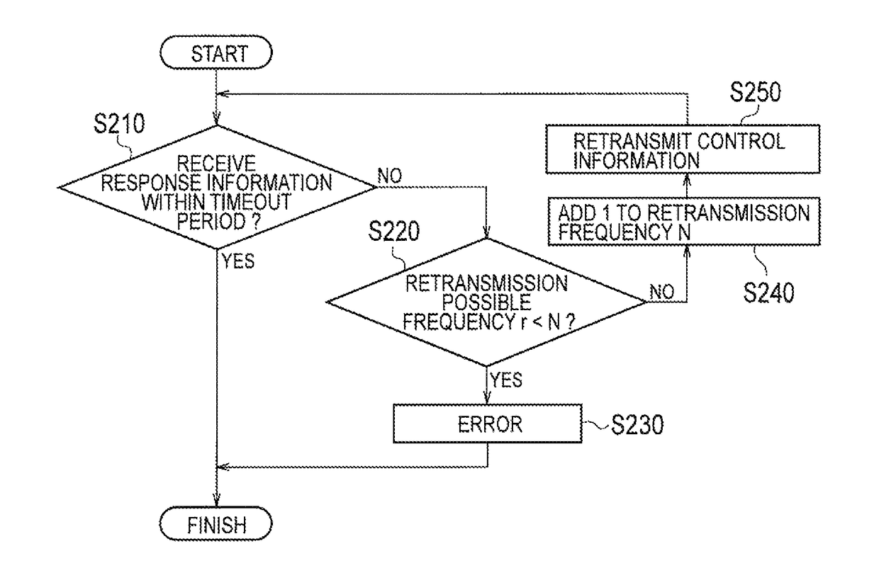
However, in a power control apparatus performing a transmission of control information in a predetermined cycle, a timeout period is set to be too long sometimes when changing the timeout period merely based on a change of number of hops.
In this case, when the power control apparatus retransmits the control information according to the retransmission control, there is a risk that congestion occurs between the retransmitted control information and control information that is to be transmitted in the next control cycle.

Method used


Image

  • Power control apparatus, power control system, and control method
  • Power control apparatus, power control system, and control method
  • Power control apparatus, power control system, and control method

Examples


first embodiment

[0027][First Embodiment]

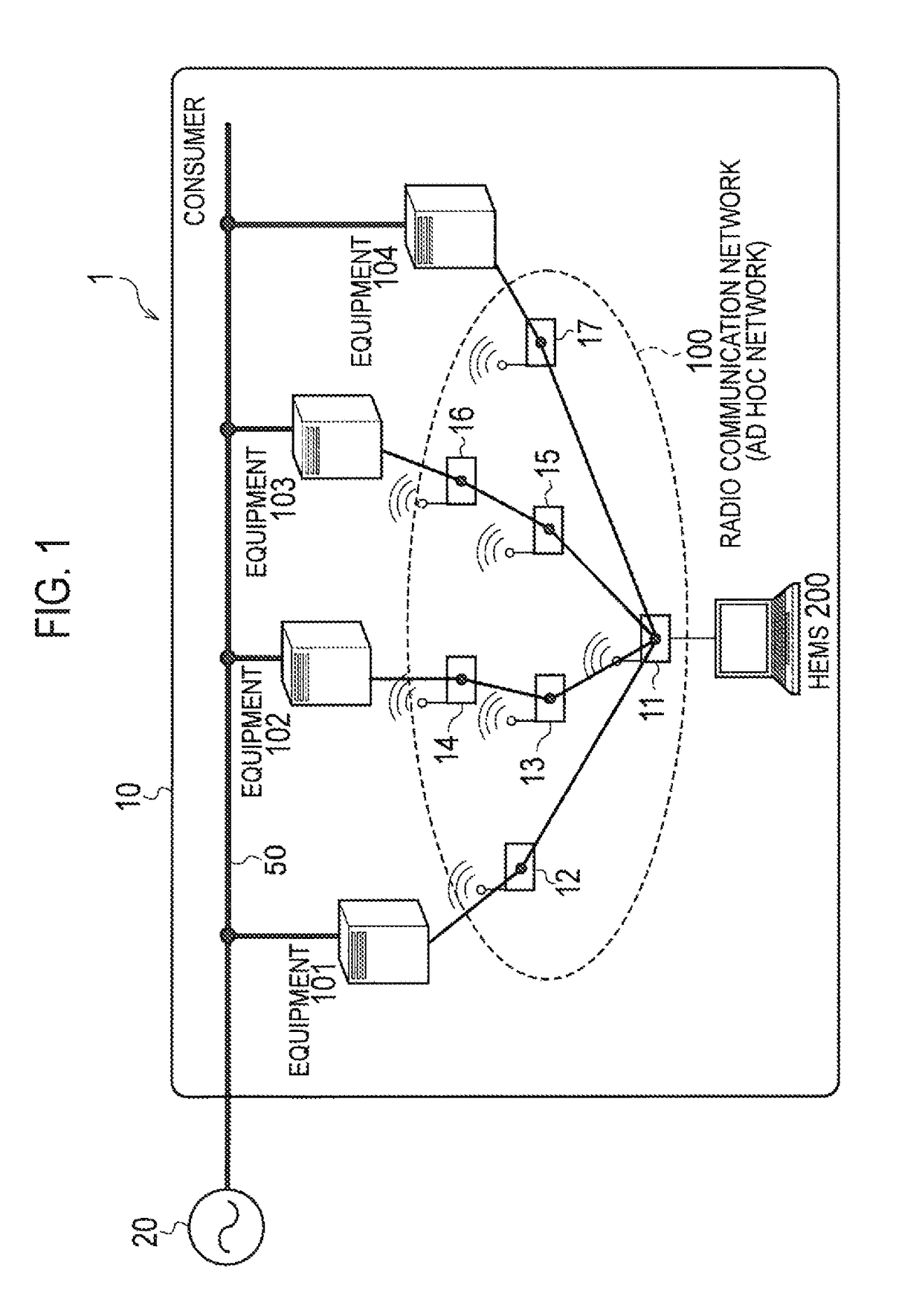
[0028]A power control system according to a first embodiment will be described. FIG. 1 is a diagram showing a power control system 1 according to the first embodiment. As shown in FIG. 1, the power control system 1 is provided in a consumer 10. In the present embodiment, the consumer 10 is assumed to be a house and the like. The power control system 1 performs a power control in the consumer 10 which is connected to a power grid 20. The power control system 1 comprises a plurality of equipment 101 to 104 provided in the consumer 10, and an HEMS 200 connecting to the plurality of equipment 101 to 104 through a radio communication network 100.

[0029]The plurality of equipment 101 to 104 perform various processes in accordance with an instruction from the HEMS 200. The plurality of equipment 101 to 104 include loads provided in a consumer, sensors, distributed power supplies, and the like. The plurality of equipment 101 to 104 may include other equipment such as ...


PUM


Abstract

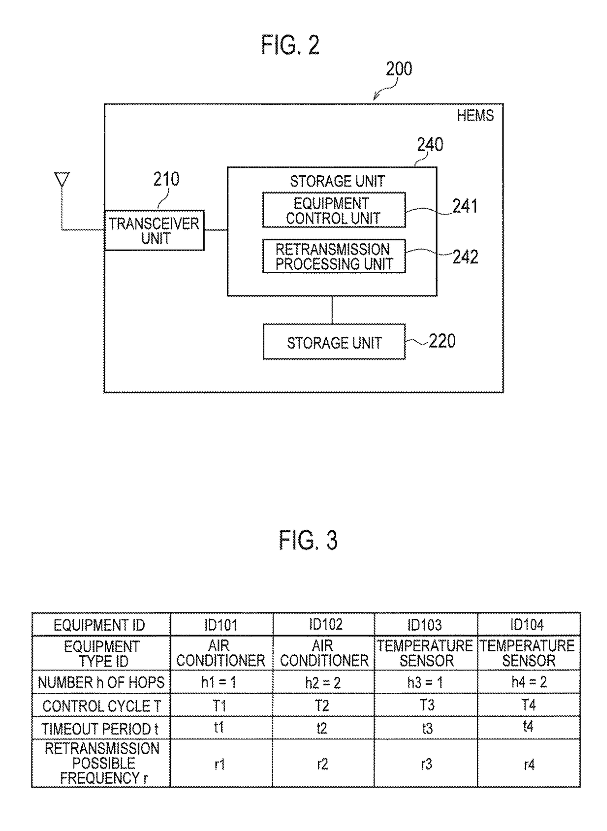
A HEMS 200 connects to equipment provided in a consumer through a communication network and controls the equipment. The HEMS 200 comprises a transceiver unit 210 transmitting control information for controlling the equipment to the equipment in each control cycle T and a control unit 240 controlling a transmission of the control information; the control unit 240 controls the transceiver unit 210 to retransmit the control information to the equipment when response information corresponding to the control information is not received within a timeout period t set to be shorter than the control cycle T from the transmission of the control information from the transceiver unit 210. The control unit 240 changes the timeout period t by controlling a retransmission possible frequency of the control information within the period of the control cycle T.

Description

TECHNICAL FIELD[0001]The present invention relates to a power control apparatus connecting to equipment provided in a consumer through a radio communication and controlling the equipment, and a control method.BACKGROUND ART[0002]It is known a power control apparatus that controls equipment such as a load provided in a consumer and a distributed power supply, and performs an optimum energy management. Among such power control apparatuses, which intended for a house is called an HEMS (Home Energy Management System).[0003]The power control apparatus described above transmits control information, which is for performing controls such as equipment state confirmation and equipment setting change, to equipment in a predetermined cycle (hereinafter, “predetermined cycle”). The equipment receiving the control information transmits response information corresponding to the control information to the power control apparatus.[0004]Here, in a power control apparatus, when transmitting control in...

Claims


Application Information

Patent Timeline
Patent Type & Authority Patents(United States)
IPC IPC(8): G05F1/66H04L1/18H04L12/28H04W52/02H04L1/00H04W84/18
CPCG05F1/66H04L1/188H04L12/2803Y02D70/144H04W84/18H04L2001/0097H04W52/0216H04W52/0219Y02D30/70
Inventor YOSHITANI, NAOHISA
Owner KYOCERA CORP
Learn More