
Semiconductor integrated circuit and design method for semiconductor integrated circuit

a technology of integrated circuits and semiconductors, applied in the field of semiconductor integrated circuits, can solve the problems of affecting clock skew, affecting the development time, and affecting the cost of masks used in semiconductor processes, etc., and achieve the effect of suppressing the influence of circuit modification on clock skew

Active Publication Date: 2008-06-12
PANASONIC SEMICON SOLUTIONS CO LTD
View PDF8 Cites 0 Cited by
  • Summary
  • Abstract
  • Description
  • Claims
  • Application Information

AI Technical Summary

Benefits of technology

The present invention aims to minimize the number of layers that need to be modified when making circuit modifications in a semiconductor integrated circuit. This is achieved by adding a dummy flipflop in parallel with the actual operation flipflop, which allows for easier modification of interconnects and reduces the impact on clock skew and crosstalk. Additionally, a circuit modification interconnect can be added to further minimize the required modifications. Overall, this invention helps to improve the efficiency and reliability of semiconductor integrated circuits.

Problems solved by technology

In this situation, the cost of masks used in a semiconductor process has risen.
This is therefore greatly disadvantageous in the aspects of cost (mask cost, etc.) and the development time.
In the case of FIG. 14, which requires rerouting of interconnects, a difference arises between the length of an interconnect to a dummy cell and the length of an interconnect to a reconnected dummy FF cell, and this may adversely affect clock skew.
Also, since clock routing is often made in consideration of signal integrity, there are concerns that congestion may occur due to the rerouting and that signal integrity measures for the modified interconnect may be insufficient.

Method used


Image

  • Semiconductor integrated circuit and design method for semiconductor integrated circuit
  • Semiconductor integrated circuit and design method for semiconductor integrated circuit
  • Semiconductor integrated circuit and design method for semiconductor integrated circuit

Examples


Embodiment Construction

[0030]Hereinafter, preferred embodiments of the present invention will be described with reference to the accompanying drawings.

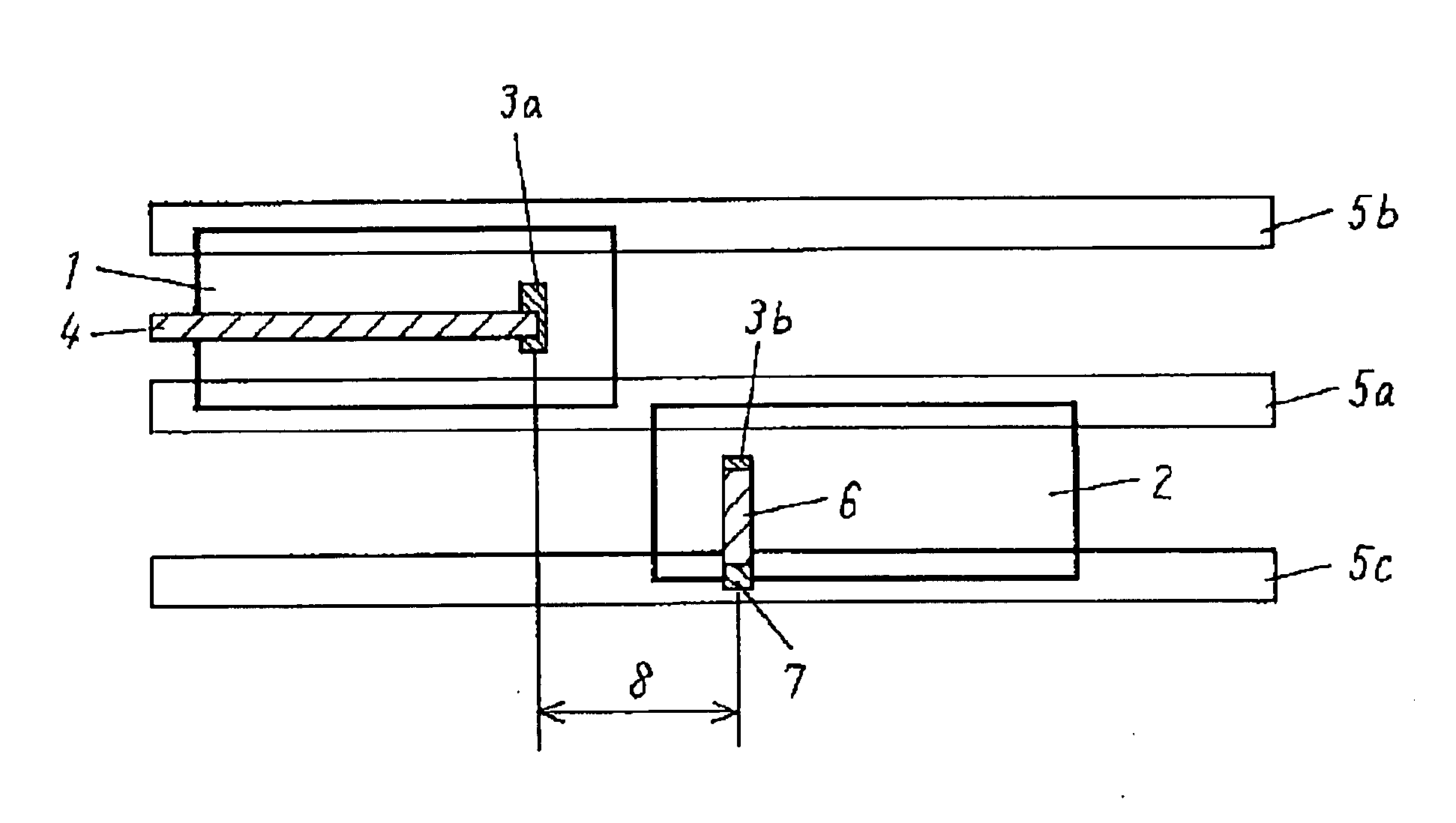
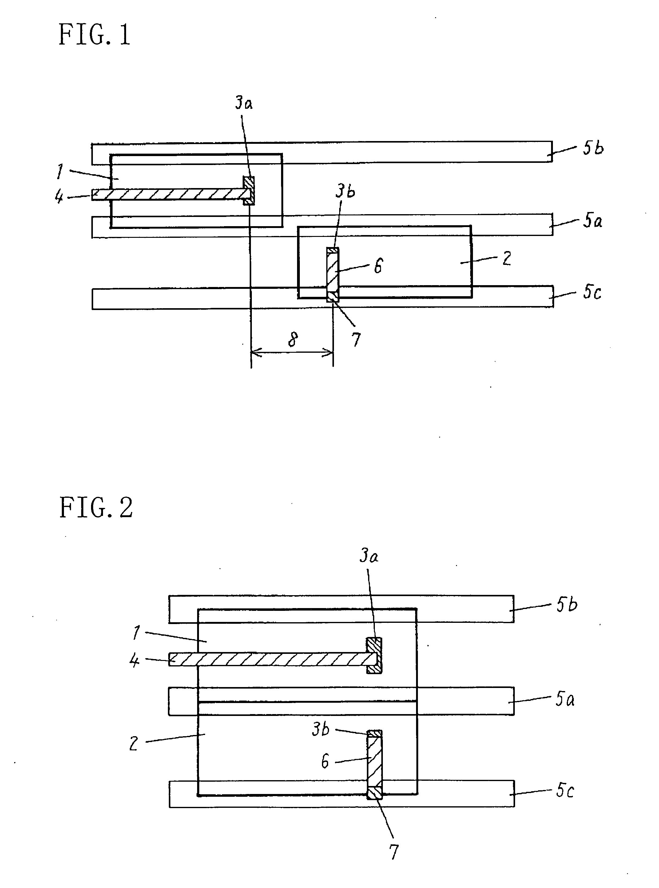
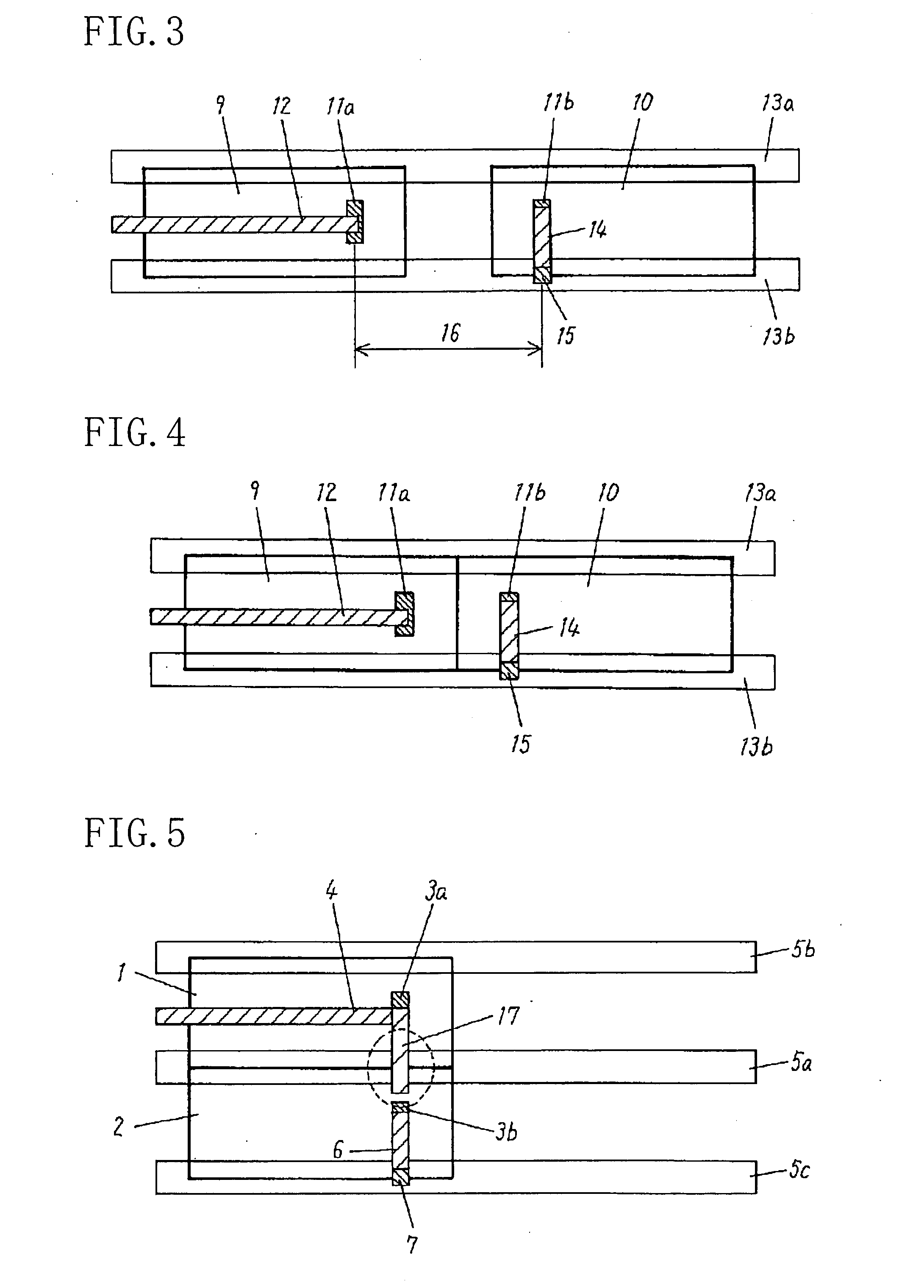
[0031]FIG. 1 is a layout diagram showing a first exemplary configuration of a semiconductor integrated circuit of an embodiment of the present invention. The semiconductor integrated circuit of FIG. 1 includes a ground line 5a, power supply lines 5b and 5c, an actual operation FF 1, and a dummy FF 2. In FIG. 1, the two power supply lines 5b and 5c are placed in parallel with the ground line 5a running in the center therebetween. The actual operation FF 1 is connected to the ground line 5a and the power supply line 5b, while the dummy FF 2 is connected to the ground line 5a and the power supply line 5c. In the operation, the ground potential is provided to the ground line 5a while the positive power supply potential is provided to the power supply lines 5b, 5c.

[0032]The actual operation FF 1 has a clock terminal 3a. The dummy FF 2, which is a flipflop of th...


PUM


Abstract

The semiconductor integrated circuit of the invention includes: two first power supply lines placed in parallel in a same interconnect layer; a second power supply line placed between the two first power supply lines in the same interconnect layer; an actual operation flipflop connected to one of the two first power supply lines and the second power supply line and having a first clock terminal; and a dummy flipflop connected to the other first power supply line and the second power supply line and having a second clock terminal. The dummy flipflop includes: a contact connected to the other first power supply line or the second power supply line; and an interconnect for connecting the second clock terminal with the contact.

Description

CROSS-REFERENCE TO RELATED APPLICATIONS[0001]This application claims priority under 35 U.S.C. §119 on Patent Application No. 2006-331553 filed in Japan on Dec. 8, 2006, the entire contents of which are hereby incorporated by reference.BACKGROUND OF THE INVENTION[0002]The present invention relates to a semiconductor integrated circuit and a design method for the same, and more particularly, to circuit modifiability in the design stage.[0003]In recent years, design rules of semiconductor integrated circuits have become finer and the semiconductor process technology has been more sophisticated. In this situation, the cost of masks used in a semiconductor process has risen. At the time of circuit modification, therefore, it has been requested to reduce the number of layers to be modified to a minimum so as to minimize the number of masks to be modified. At the time of modification for a clock system, it has been additionally requested to suppress a skew variation that may occur with the...

Claims


Application Information

Patent Timeline
Patent Type & Authority Applications(United States)
IPC IPC(8): G06F17/50H03K19/173
CPCG06F2217/64H01L28/20H01L27/11807G06F2115/06
Inventor NAGATANI, TAKAHIROIMAIZUMI, MITSUHIRO
Owner PANASONIC SEMICON SOLUTIONS CO LTD
Learn More