Eureka AIR delivers breakthrough ideas for toughest innovation challenges, trusted by R&D personnel around the world.

Valve control in an HVAC system with sensors

a valve control and sensor technology, applied in the field of valve control in the hvac system with sensors, can solve the problems of permanent or temporary sensor faults and increase accordingly, and achieve the effect of improving the tolerance of the hvac system

Active Publication Date: 2018-03-20
BELIMO HOLDING AG
View PDF17 Cites 1 Cited by
  • Summary
  • Abstract
  • Description
  • Claims
  • Application Information

AI Technical Summary

Benefits of technology

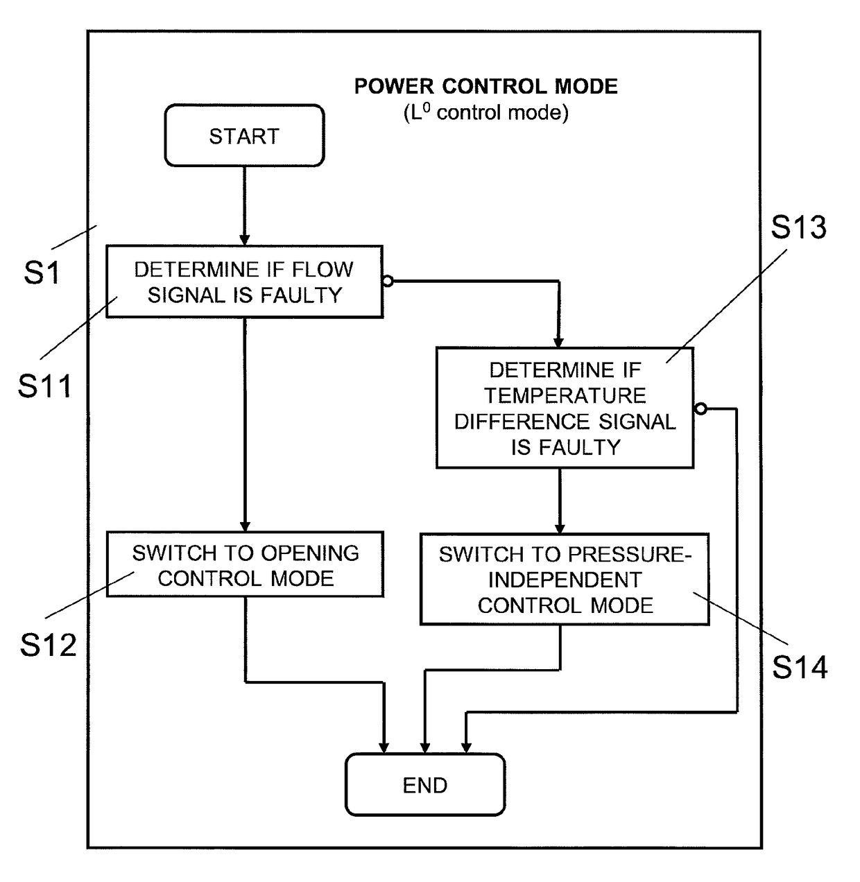
[0007]It is an object of this invention to provide a method and a device for controlling the opening of a valve in an HVAC, which method and device do not have at least some of the disadvantages of the prior art. In particular, it is an object of the present invention to provide a method and a device for controlling opening of a valve in an HVAC system, which method and device improve the tolerance of the HVAC system with respect to sensor faults.
[0018]Switching back to the default control mode, if and when the default sensor is no longer faulty, has the advantage that the method dynamically switches back to the preferred default control mode when the respective sensor and / or its operation and / or connection has been replaced or repaired, respectively. As will become more readily apparent in the following description, the fallback control mode is generally less sophisticated and / or shows lower control performance, because it does not rely on the default sensor signal. It is accordingly desirable to switch back to the default control mode, if and when the default sensor signal is valid again and the default control mode is accordingly available again.

Problems solved by technology

With the number of sensors or sensor systems that are involved in the control of an HVAC system, as well as the complexity of the sensors or sensor systems, the risk of permanent or temporary sensor faults increases accordingly.

Method used


Image

  • Valve control in an HVAC system with sensors
  • Valve control in an HVAC system with sensors
  • Valve control in an HVAC system with sensors

Examples


Embodiment Construction

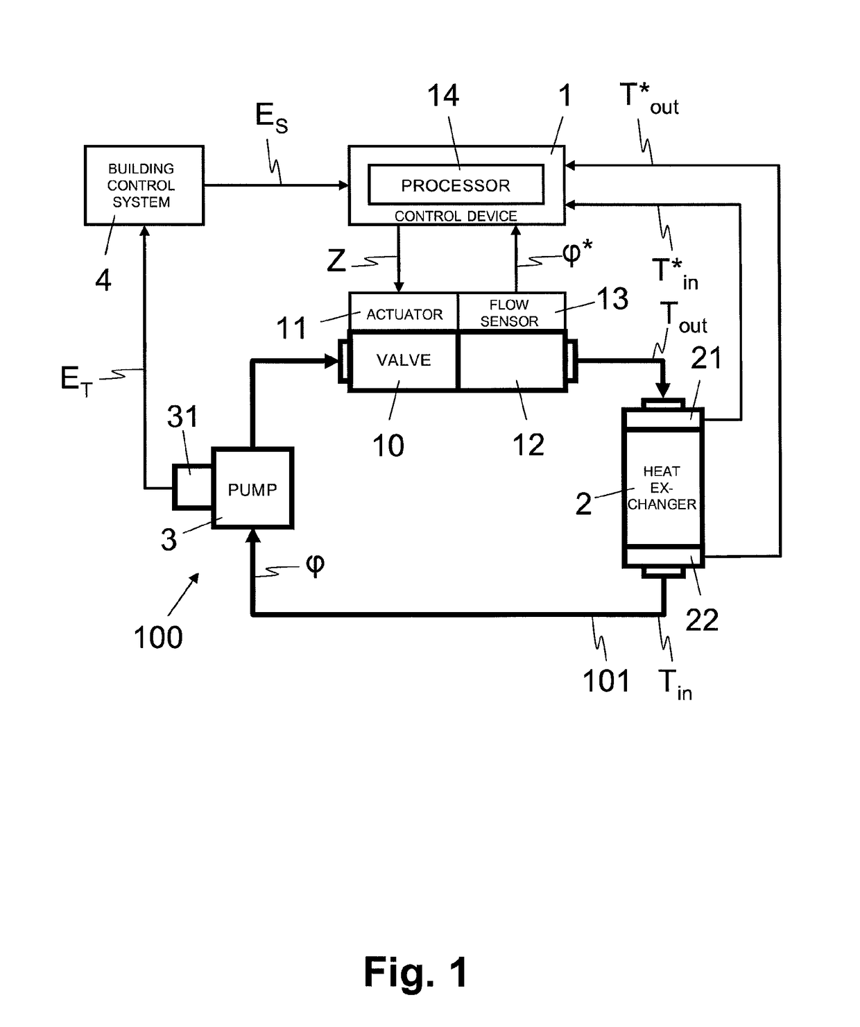
[0060]In FIG. 1, reference numeral 100 refers to an HVAC system with a fluid circuit 101 comprising a pump 3, a valve 10, a heat exchanger 2, for example a heat exchanger for heating or cooling a room, with the components of the fluid circuit being interconnected by way of pipes. The valve 10 is provided with an actuator 11, for example an electrical motor, for opening and closing the valve 10 and thus controlling the flow through the fluid circuit 101, using different positions (or sizes of orifice) of the valve 10, corresponding to different degrees of opening of the valve 10. Further, the pump 3 may vary the flow through the fluid circuit 101.

[0061]As illustrated schematically, the HVAC system 100 further comprises an optional building control system 4 connected to the valve 10 or actuator 11, respectively. One skilled in the art will understand that the depiction of the HVAC system 100 is very simplified and that the HVAC system 100 may include a plurality of fluid circuits 101,...


PUM


Abstract

The present disclosure is directed towards a method of controlling opening of a valve (10) in an HVAC system (100). The method includes controlling the opening of the valve (10) according to a default control mode in dependence of a default sensor signal. The method further includes determining, while controlling the opening of the valve (10) according to the default control mode, whether the default sensor signal is faulty and switching, in case of the default sensor signal being faulty, to controlling the opening of the valve (10) according to a fallback control mode, with the opening of the valve (10) being controlled independently of the faulty sensor signal in the fallback control mode. The present invention is further directed towards a corresponding control device opening of a valve (10) in an HVAC system as well as a corresponding computer program product.

Description

FIELD OF THE INVENTION[0001]The present invention relates to a method and a device for controlling the opening of a valve in a Heating, Ventilating and Air Conditioning (HVAC) system. Specifically, the present invention relates to a method and a control device for controlling the opening of a valve in an HVAC system to regulate the flow of a fluid through a heat exchanger of the HVAC system and to thereby adjust the amount of energy exchanged by the heat exchanger.BACKGROUND OF THE INVENTION[0002]By regulating the flow of fluid through heat exchangers of an HVAC system, it is possible to adjust the amount of energy exchanged by the heat exchangers, for example to adjust the amount of energy that is delivered per time by a heat exchanger to heat or cool a room in a building or the amount of energy that is drawn by a chiller per time for cooling purposes. While the fluid transport through the fluid circuit of the HVAC system is driven by one or more pumps, the flow is typically regula...

Claims


Application Information

Patent Timeline
Patent Type & Authority Patents(United States)
IPC IPC(8): F28F27/00F24F11/00
CPCF24F11/30F28F27/00F24F11/83F24F11/32F24F11/84F24F11/49G05B2219/37333
Inventor AEBERHARD, RONALDTHUILLARD, MARCMAZENAUER, PHILIPP
Owner BELIMO HOLDING AG
Why Eureka
Eureka Blog
Learn More