
Detachable chainring assembly

a chainring and assembly technology, applied in mechanical equipment, transportation and packaging, and hoisting equipment, etc., can solve the problems of insufficient securing space for chainrings, the inability to replace chainrings for road bikes, and the inability to adapt to the crank arm and the corresponding crank rings of the conventional crank assembly adapted for mountain bikes, etc., to achieve the improvement of stability of the locking part for securing the second chainring, increase the economic benefits, and increase the diversity of adapted

Active Publication Date: 2018-03-13
TH IND
View PDF5 Cites 13 Cited by
  • Summary
  • Abstract
  • Description
  • Claims
  • Application Information

AI Technical Summary

Benefits of technology

The detachable chainring assembly increases compatibility with various bicycles, reduces weight, and allows for cost-effective replacement of individual chainrings, enhancing stability and economic benefits by eliminating the need for spider components and enabling secure attachment without spiders.

Problems solved by technology

However, the spider of the conventional crank assembly may cause a limitation about selecting the chainrings and the corresponding crank arm.
For example, owing to the structure limitation of the spider, the crank arm and the chainrings of the conventional crank assembly adapted for the mountain bike are limited to be only suited to being provided with the mountain bike, that is to say, the crank arm and the chainrings of the conventional crank assembly adapted for the mountain bike cannot be replaceable for the road bike.
Simultaneously, the chainrings have to keep some space for being secured with the spider such that the chainring may not be enough securing space for another element used to be stably secured with another chainring.
However, when one of the two integrated chainrings of the crank assembly has a breakdown and need to be displaced a new chainring, the two integrated chainrings must be simultaneously displaced with two new chainrings such that the users disburse more cost.

Method used


Image

  • Detachable chainring assembly
  • Detachable chainring assembly
  • Detachable chainring assembly

Examples


Embodiment Construction

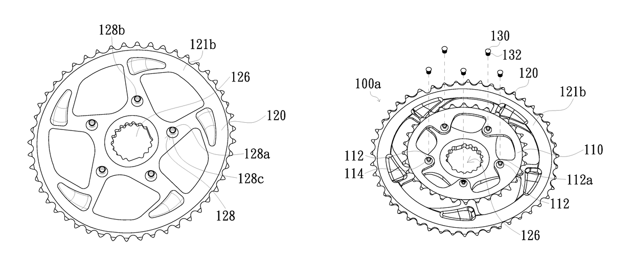
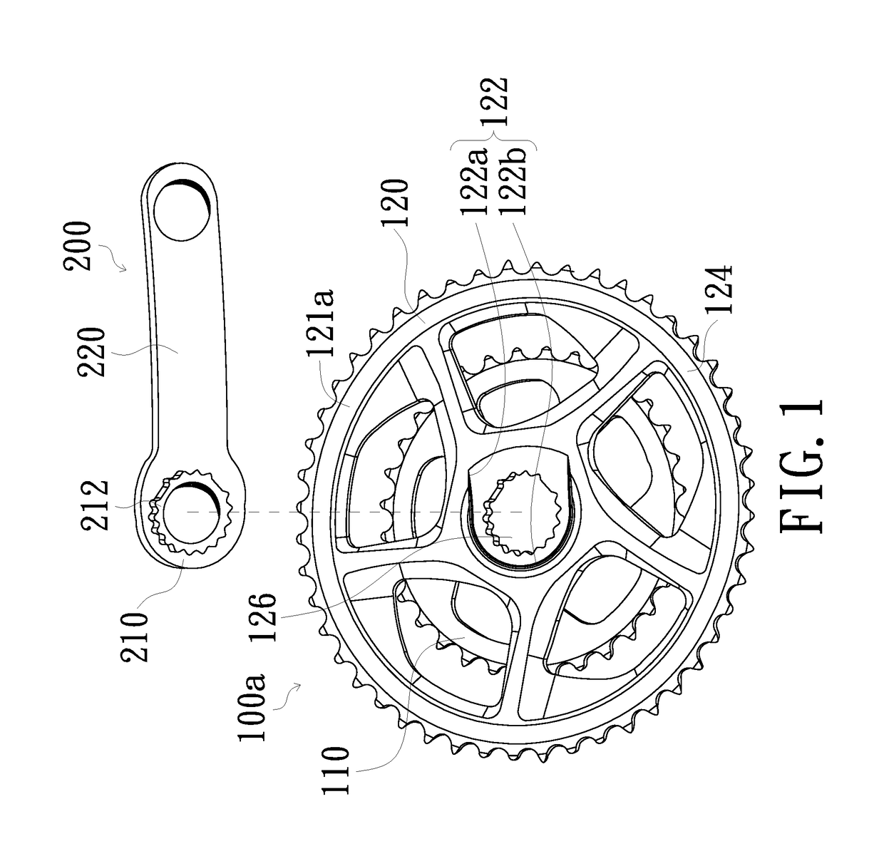
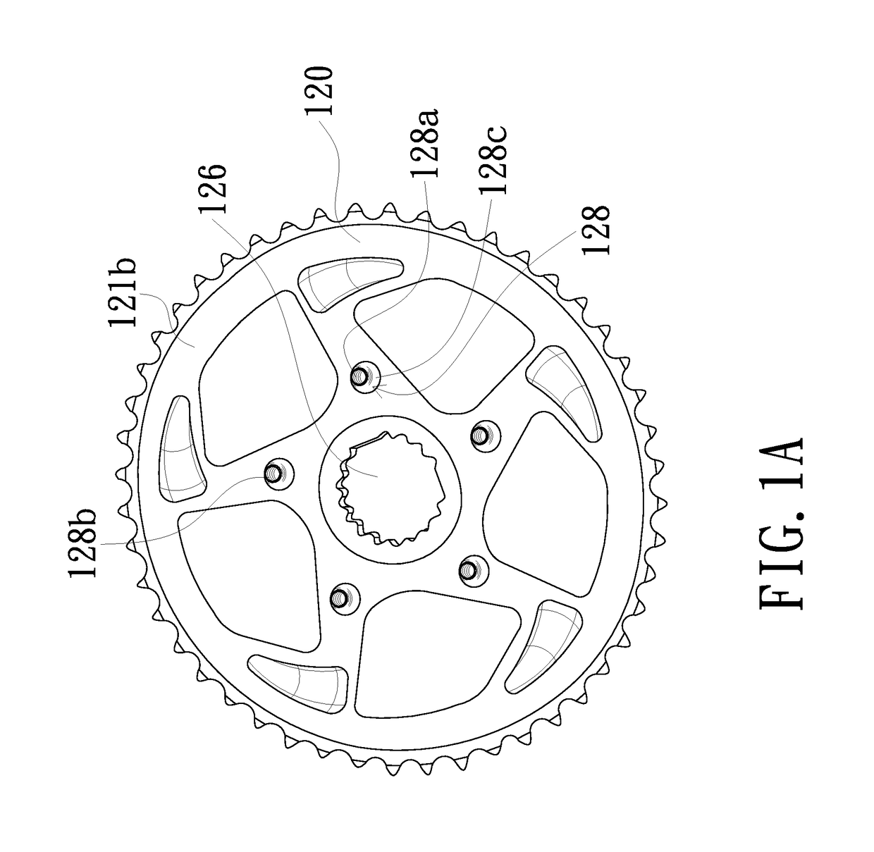
[0023]Please refer to FIG. 1, FIG. 1A, and FIG. 2, FIG. 1 shows a perspective view of a detachable chainring assembly according to an embodiment of the present disclosure, FIG. 1A shows a perspective view of another perspective of a second chainring of the detachable chainring assembly of FIG. 1, and FIG. 2 shows a perspective view of another perspective of the detachable chainring assembly of FIG. 1. As shown in FIG. 1, FIG. 1A, and FIG. 2, the detachable chainring assembly 100a of the embodiment is adapted for a crank assembly without a spider. A crank arm 200 may be directly secured to the detachable chainring assembly 100a of the embodiment and need not coordinate with any spiders to be jointly secured to the detachable chainring assembly 100a.

[0024]The detachable chainring assembly 100a of the embodiment includes a first chainring 110, a second chainring 120 and a plurality of locking parts 130; the plurality locking parts 130 are detachably secured to the first chainring 110 ...


PUM


Abstract

A detachable chainring assembly includes a first chainring, a second chainring and a locking part. The first chainring includes a first through hole. The second chainring includes a first surface, a second surface, a driven hole, and a plurality of first protrusion parts. The second surface is opposite to the first surface. The driven hole runs through the first surface and the second surface for securing a driving portion of a crank arm. The first protrusion parts protrude from the second surface and are disposed around the driven hole, and at least one of the first protrusion parts has a first locked hole. The locking part is detachably secured to the first through hole and the first locked hole such that the first chainring and the second chainring are jointly secured to each other via the locking part.

Description

FIELD OF THE INVENTION[0001]The present invention relates to a detachable chainring assembly, and more particularly to a detachable chainring assembly adapted for bicycles.BACKGROUND OF THE INVENTION[0002]Recently, a crank assembly adapted for a speed-changing bicycle includes a crank arm and at least two chainrings secured with the crank arm. One of the chainrings may be connected to a rear freewheel which is connected to a hub of a rear wheel via a chain. Thus, when the rider pedals to drive one of the chainrings being rotated clockwise, the chain movably drives the rear freewheel rotating clockwise such the rear wheel rotatably drives the bicycle moving forward.[0003]The conventional crank assembly is formed by the crank arm secured with the chainrings via a spider. However, the spider of the conventional crank assembly may cause a limitation about selecting the chainrings and the corresponding crank arm. For example, owing to the structure limitation of the spider, the crank arm...

Claims


Application Information

Patent Timeline
Patent Type & Authority Patents(United States)
IPC IPC(8): B62M9/10F16H55/30
CPCF16H55/303B62M9/105
Inventor WU, POKI
Owner TH IND
Learn More