
Wireless communication system for reporting radio link information of a first radio link via a second radio link when radio link problem has occurred in the first radio link

a radio link and information technology, applied in the field of wireless communication technology, can solve the problems of user equipment being easily subject to radio link failure, affecting the operation of small cells in hot districts, and increasing the density of small cells, so as to facilitate the rapid recovery of user equipment, improve the robustness of mobility, and increase the transmission power

Active Publication Date: 2018-03-06
SONY CORP
View PDF10 Cites 1 Cited by
  • Summary
  • Abstract
  • Description
  • Claims
  • Application Information

AI Technical Summary

Benefits of technology

The present patent aims to provide a solution to quickly solve the radio link problem in a heterogeneous network, and improve the robustness of mobility. The patent proposes an architecture of dual-connection, which allows the user equipment to quickly recover from radio link failure by simultaneously connecting with two different base stations. This separation of control plane / user plane, allows the user equipment to maintain a better channel quality with the small base station, which provides better coverage only for hot districts. The architecture of dual-connection also allows the user equipment to quickly solve the radio link problem with one of the normal nodes, which can assist the user equipment in reducing service interruption time and enhancing mobility.

Problems solved by technology

In a future network, deployment of the small cells in a hot district becomes much denser and inter-cell interference becomes much severer.
Meanwhile, the user equipment might easily subject to the radio link failure in a scene of a heterogeneous network with dense deployment due to limited coverage ranges of the small cells.

Method used


Image

  • Wireless communication system for reporting radio link information of a first radio link via a second radio link when radio link problem has occurred in the first radio link
  • Wireless communication system for reporting radio link information of a first radio link via a second radio link when radio link problem has occurred in the first radio link
  • Wireless communication system for reporting radio link information of a first radio link via a second radio link when radio link problem has occurred in the first radio link

Examples


Embodiment Construction

[0043]Exemplary embodiments of the present disclosure will be described below in conjunction with the accompanying drawings. For the sake of clarity and conciseness, not all the features of practical implementations are described in the specification. However, it is to be appreciated that numerous implementation-specific decisions shall be made during developing any of such practical implementations so as to achieve the developer's specific goals, for example, to comply with system- and business-related constraining conditions which will vary from one implementation to another. Moreover, it shall also be appreciated that such a development effort might be very complex and time-consuming but may simply be a routine task for those skilled in the art benefiting from this disclosure.

[0044]It shall further be noted that only those device structures and / or process steps closely relevant to the solutions of the disclosure are illustrated in the drawings while other details less relevant to...


PUM


Abstract

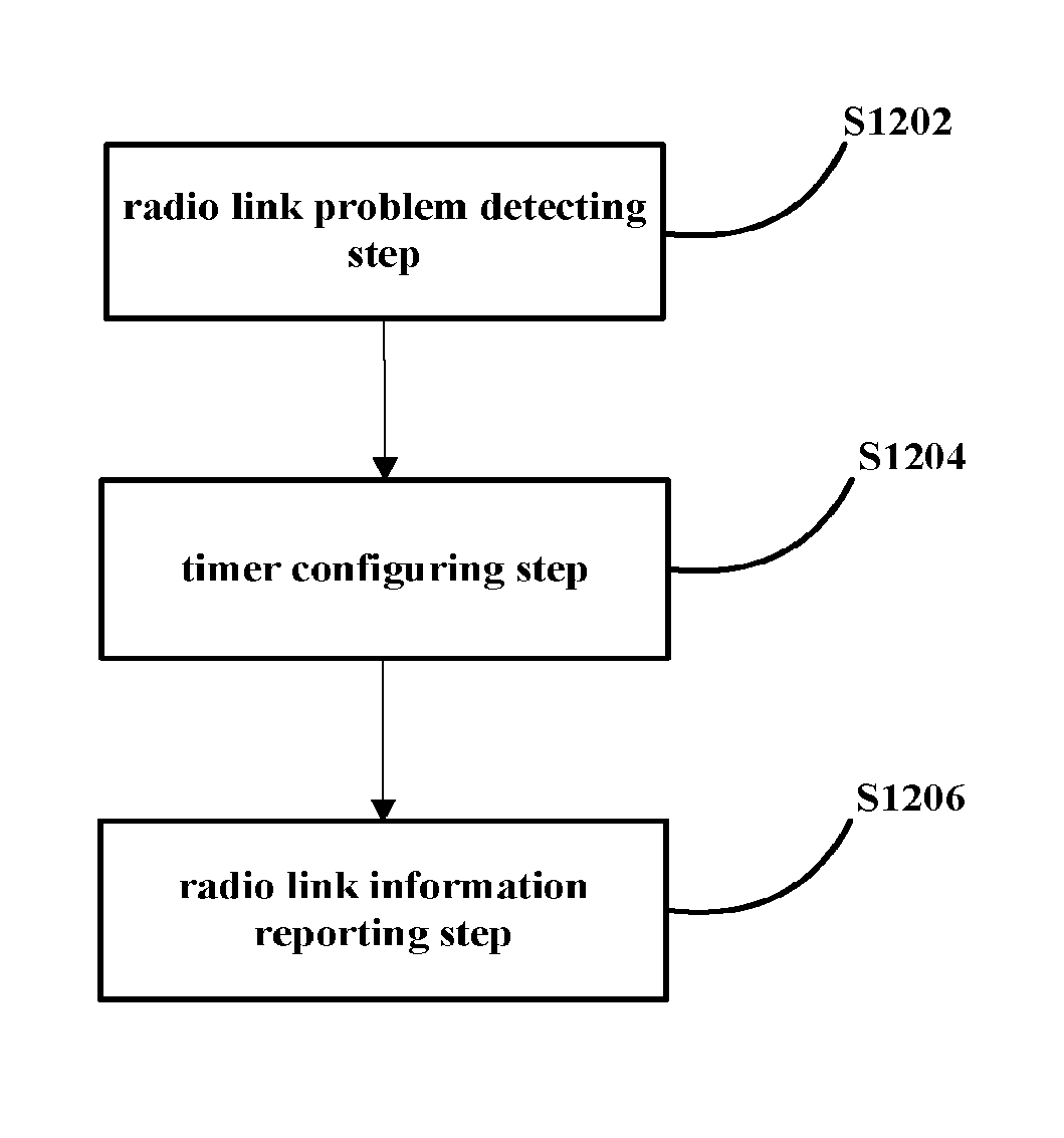
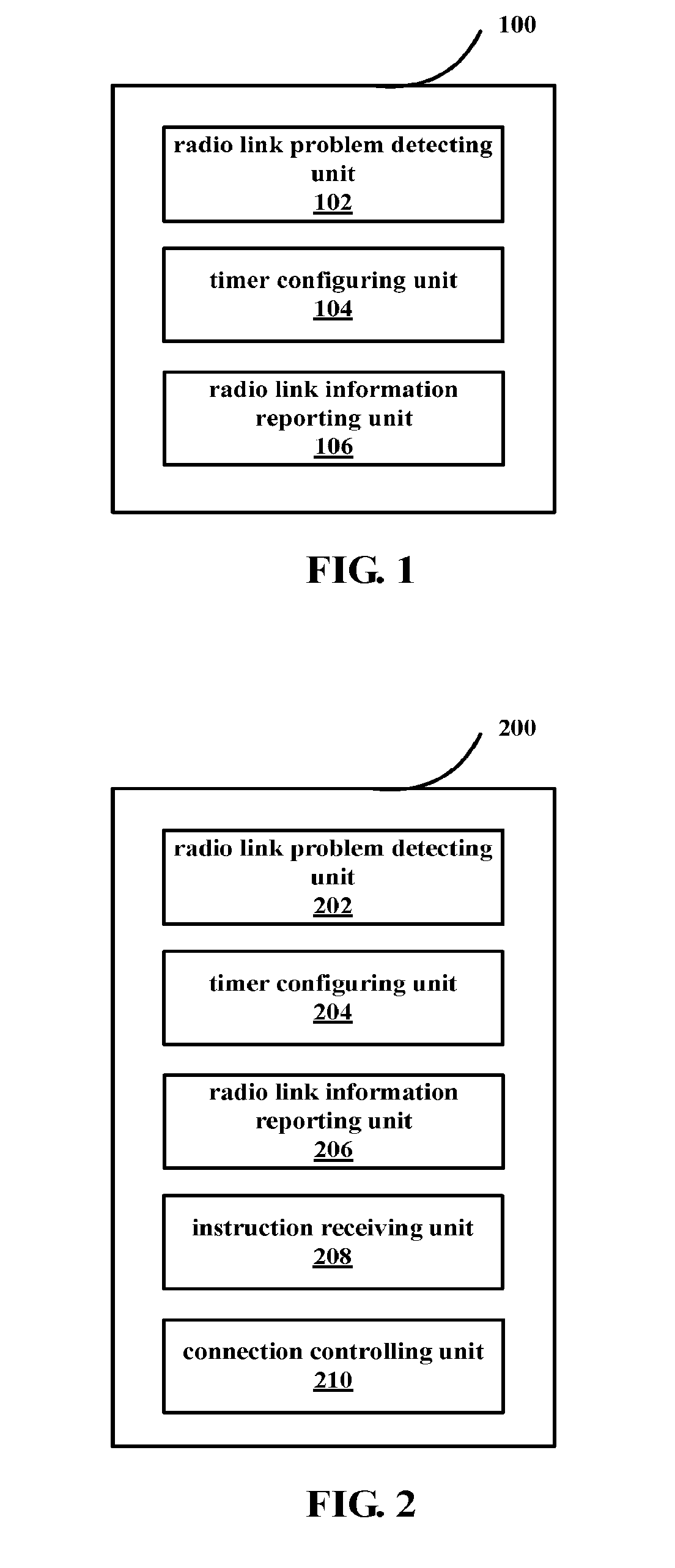
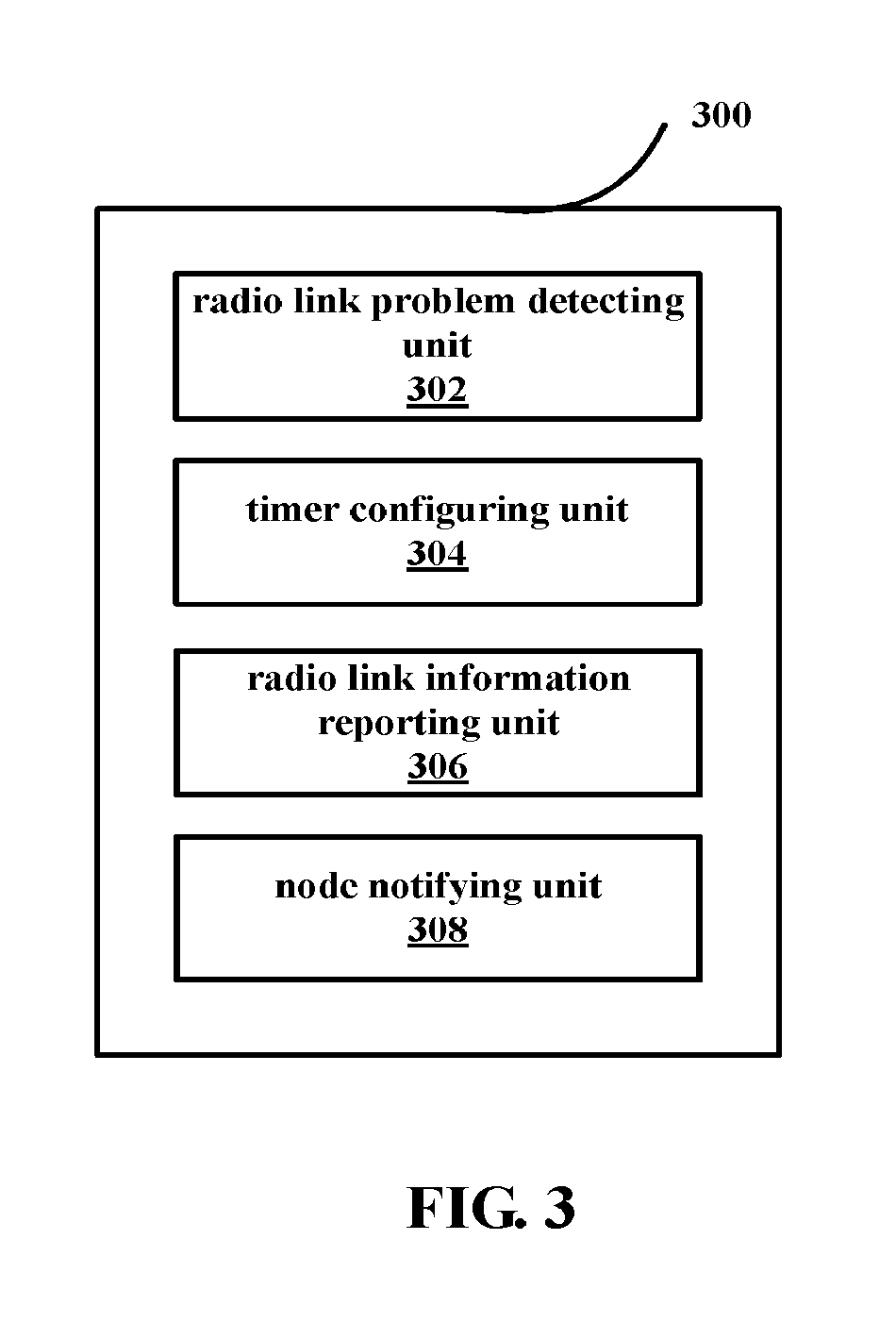
A wireless communication system, an apparatus in the wireless communication system and a method. The apparatus at a user equipment side in the wireless communication system includes: a wireless link problem detector, detecting a first wireless link between a first node and a user equipment to determine whether a wireless link problem occurs; a timer configuration unit, which starts a first timer when detecting that the wireless link problem occurs on the first wireless link, wherein the user equipment considers that a wireless link failure event occurring on the first wireless link is detected when the first timer expires; and a wireless link information reporting unit, which reports content including wireless link information of the first wireless link to a second node through a second wireless link between the user equipment and the second node when detecting that the wireless link problem occurs on the first wireless link.

Description

FIELD OF THE INVENTION[0001]The present disclosure relates to the field of wireless communication technology, and more particularly, to a device on user equipment side in a wireless communication system, a device, a method for use in the wireless communication system and a wireless communication system, which are capable of quickly solving a radio link problem.BACKGROUND OF THE INVENTION[0002]When a signal of user equipment has been subjected to severe interference or deep attenuation, the user equipment may undergo a radio link failure. The radio link failure will result in interruption of service transmission, during which the user equipment can not transmit or receive any data service. Further, a too long time of interruption of connection will produce a negative effect on an application layer, thereby lowering user experience.[0003]In order to account for amount of mobile data which increases exponentially in a network, small cells are deployed in hot regions in a heterogeneous ...

Claims


Application Information

Patent Timeline
Patent Type & Authority Patents(United States)
IPC IPC(8): H04W24/00H04W24/10H04W24/02H04W24/08
CPCH04W24/08H04W24/02H04W76/19H04W76/28H04W76/38H04W24/10H04W36/00692H04W24/04H04W36/305
Inventor XU, XIAODONGHONG, YATENGLIU, YA
Owner SONY CORP
Learn More