
Method for controlling an alternating current electric machine, and a frequency converter

a technology of alternating current electric machines and frequency converters, applied in the direction of control systems, pulse manipulation, pulse techniques, etc., can solve the problems of line current and further in the power grid, periodic disturbance, current distortion, etc., and achieve the effect of reducing the

Active Publication Date: 2018-03-06
KONE CORP
View PDF7 Cites 1 Cited by
  • Summary
  • Abstract
  • Description
  • Claims
  • Application Information

AI Technical Summary

Benefits of technology

This patent describes a method to improve the performance of electric machines connected to a power network. The method involves using a compensation term to remove the distortion caused by harmonics in the machine's current and power distribution. By measuring the position of the machine's rotor and updating the compensation term regularly, the method can effectively reduce distortion in the network. The method can be implemented using a frequency converter and can be used in a variety of electric machine designs. This patent provides a solution for reducing harmonics in power networks and improving the efficiency of electric machines.

Problems solved by technology

The harmonics of the electric machine may cause periodic disturbance, such as torque ripple of electric machine, current distortion resulting from rotation of the electric machine and vibration / noise of the electric machine, among others.
In prior art, the harmonic content of the electric machine had the effect that power was distributed irregularly from power line to the electric machine and from electric machine to the power line, therefore causing distortion in line current and further in power grid.

Method used


Image

  • Method for controlling an alternating current electric machine, and a frequency converter
  • Method for controlling an alternating current electric machine, and a frequency converter
  • Method for controlling an alternating current electric machine, and a frequency converter

Examples


Embodiment Construction

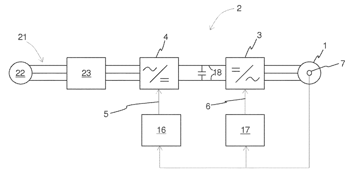
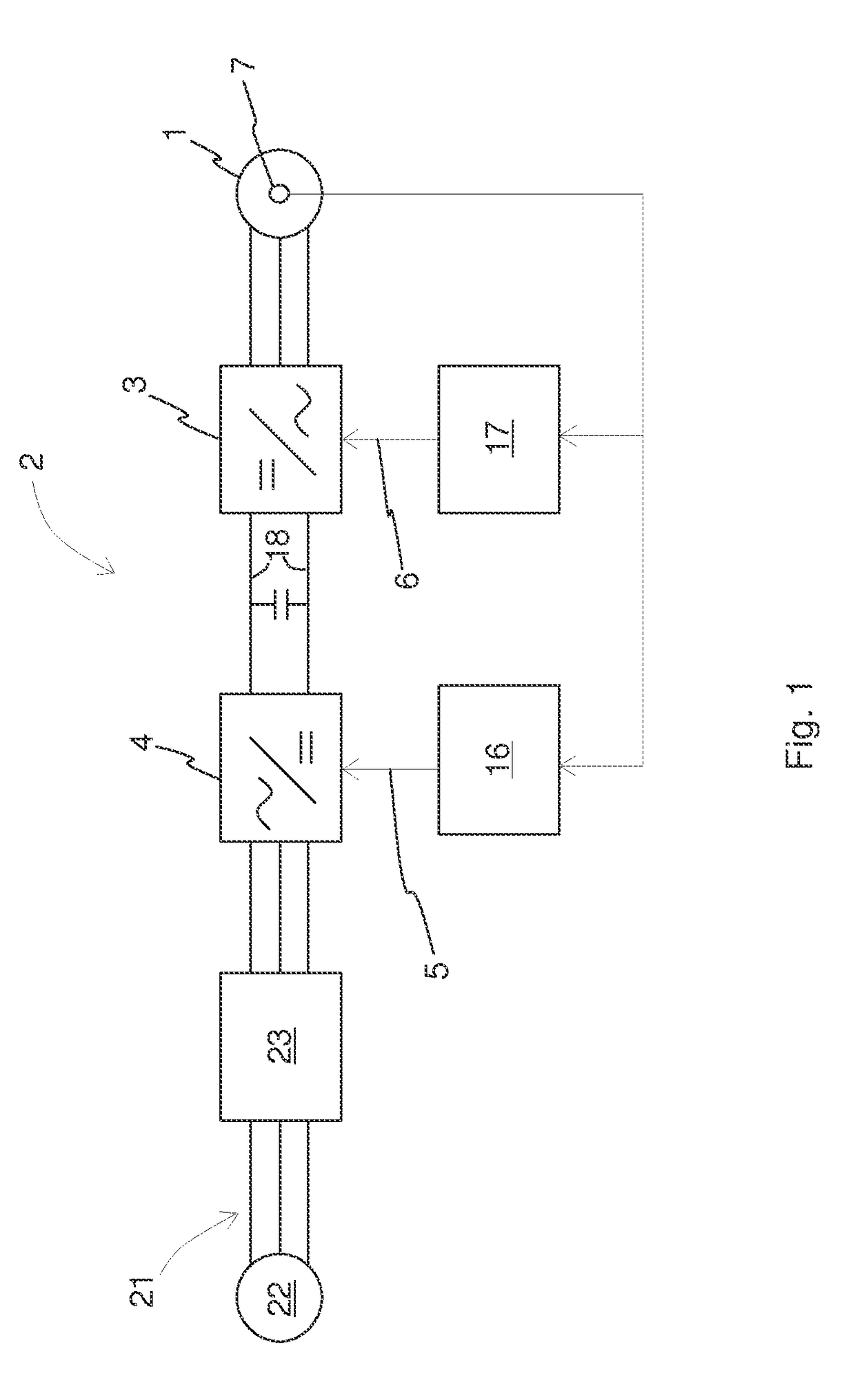
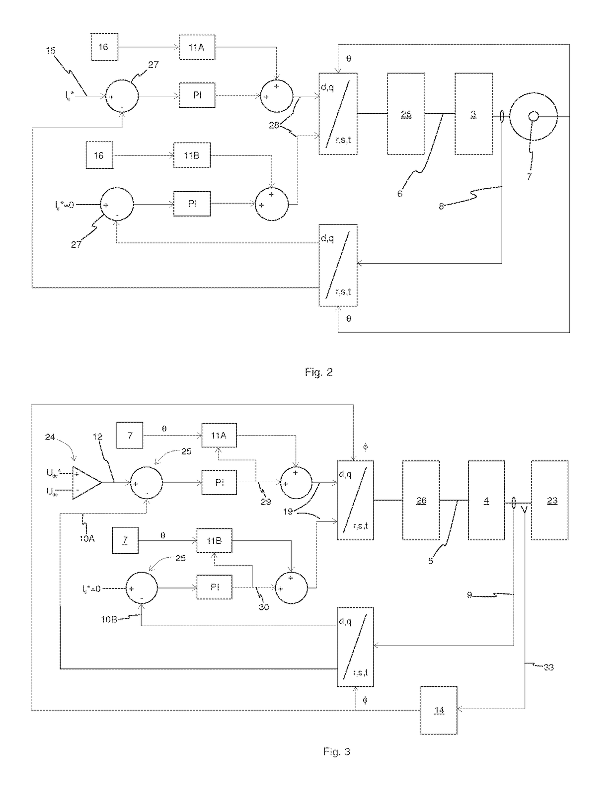
[0029]For the sake of intelligibility, in FIGS. 1-4 only those features are represented which are deemed necessary for understanding the invention. Therefore, for instance, certain components / functions which are widely known to be present in corresponding art may not be represented.

[0030]In the description same references are always used for same items.

[0031]Frequency converter 2 of FIG. 1 comprises a machine bridge 3, which is connected to a 3-phase alternating current electric machine 1 for controlling the alternating current electric machine 1. Machine bridge 3 comprises igbt transistors (insulated gate bipolar transistors) arranged to a 2-level, 3-phase inverter configuration, as is known in the art. Machine bridge igbt transistors are operable to supply voltage of variable amplitude and frequency to the windings of electric machine 1. In one embodiment the alternating current electric machine 1 is a permanent magnet synchronous electric motor. In another embodiment the alternat...


PUM


Abstract

Invention is related to a method for controlling an alternating current electric machine with a frequency converter including a controllable machine bridge and a controllable line bridge, and a corresponding frequency converter. The method comprises calculating a line bridge control signal, controlling line current through the line bridge using the line bridge control signal, measuring or estimating rotor pole position of the electric machine, calculating a machine bridge control signal as a function of the rotor pole position, updating the machine bridge control signal when the rotor pole position changes, and controlling current of the electric machine through the machine bridge using the machine bridge control signal.

Description

FIELD OF THE INVENTION[0001]The invention relates to a method for controlling an alternating current electric machine with a frequency converter, and a corresponding frequency converter. The alternating current electric machine may be an alternating current electric motor or an alternating current electric generator.BACKGROUND OF THE INVENTION[0002]Alternating current electric machines, such as motors and generators, may be operated with a frequency converter. Frequency converter may be connected between a power line and the electric machine. The power line may be further connected to a power grid. Frequency converter may include an inverter which provides variable voltage and variable frequency supply voltage to the windings of the alternating current electric machine. Frequency converter may also include a line bridge which supplies electric power to / from the power line.[0003]When operating, a magnetic flux wave travels in a magnetic circuit inside the electric machine. Magnetic f...

Claims


Application Information

Patent Timeline
Patent Type & Authority Patents(United States)
IPC IPC(8): H03K5/00H02P29/50H02P6/10H02P6/06
CPCH02P6/10H02P29/50H02P2209/07H02P6/06
Inventor STOLT, LAURI
Owner KONE CORP
Learn More