
FMCW radar self-test

a self-testing and radar technology, applied in the field of self-testing of radar devices, can solve the problems of false targets, false detection results, and inability to replicate the complete hardware chain of the sensor in parallel, and achieve the effect of improving the self-test of the radar

Active Publication Date: 2018-03-06
ARRIVER SOFTWARE AB
View PDF7 Cites 6 Cited by
  • Summary
  • Abstract
  • Description
  • Claims
  • Application Information

AI Technical Summary

Benefits of technology

[0007]An object of embodiments of the invention herein is to provide improved self-test of a radar.
[0010]Advantageously this enables a high ASIL rating of the FMCW radar device to be obtained without requiring advanced hardware. This may also enable the support of a high safety level system functionality with only a single signal processing chain. Advantageously the processing can be performed very quickly and when needed.

Problems solved by technology

Single point of failures (SPOFs) inside the sensor hardware are generally not only difficult to detect, SPOFs can also result in false targets or incorrect calculation of target parameters.
It is generally considered to be too expensive to replicate the complete hardware chain of the sensor in a parallel, truly redundant way to detect such failures.
However, the overall radar detecting system is often required to have more than one radar sensor.
This makes it difficult or expensive to realize a high automotive safety integrity level (ASIL) at the hardware stage in a sensor development.

Method used


Image

  • FMCW radar self-test
  • FMCW radar self-test
  • FMCW radar self-test

Examples


Embodiment Construction

[0026]The invention will now be described more fully hereinafter with reference to the accompanying drawings, in which certain embodiments of the invention are shown. This invention may, however, be embodied in many different forms and should not be construed as limited to the embodiments set forth herein; rather, these embodiments are provided by way of example so that this disclosure will be thorough and complete, and will fully convey the scope of the invention to those skilled in the art. Like numbers refer to like elements throughout the description.

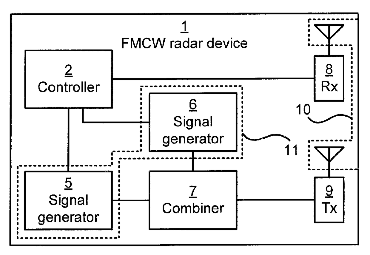
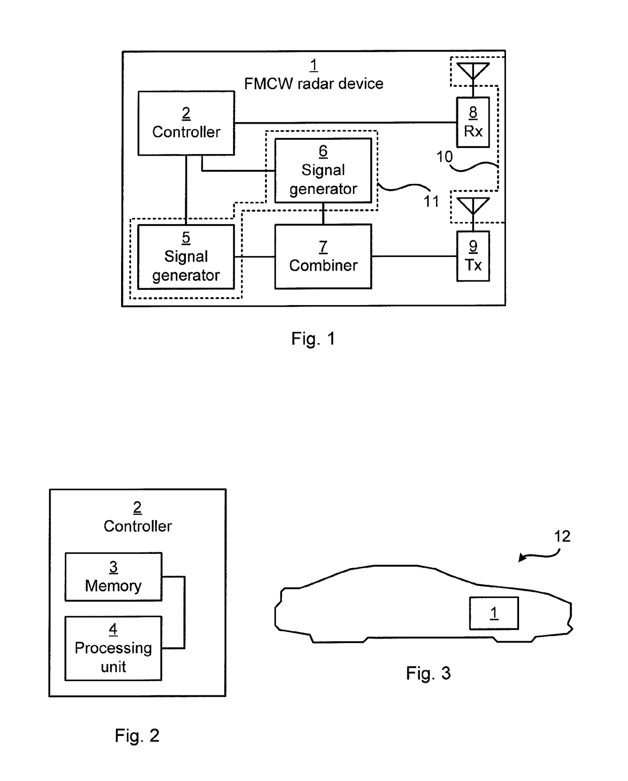
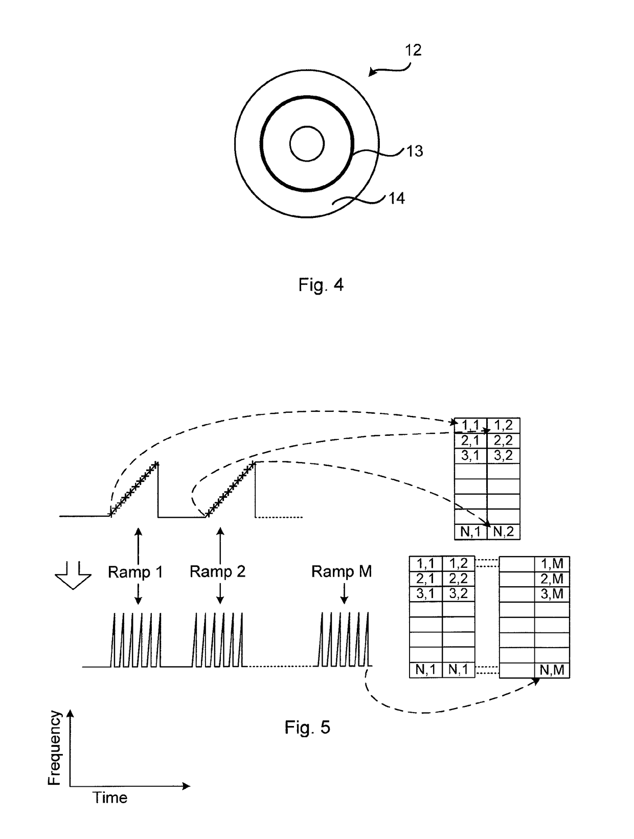
[0027]FIG. 1 is a schematic diagram showing functional modules of a continuous wave frequency-modulated (FMCW) radar device 1. In general terms, FMCW radar is a short range measuring radar capable of determining distance. The FMCW radar devices provide high reliability by providing distance measurement along with speed measurement. This kind of radar device may be used as an early-warning radar, and / or a proximity sensor. Doppler sh...


PUM


Abstract

A self-testing method of a frequency-modulated continuous-wave (FMCW) radar device. A transmission signal having an object detection signal and a self-test signal superimposed on the object detection signal is transmitted. The self-test signal represents at least one virtual target. A reception signal is received. The reception signal is a received version of the transmission signal. Presence of the at least one virtual target in the reception signal is determined. A lack of presence of the virtual target in the reception signal provides an indication of hardware failure of the FMCW radar device.

Description

CROSS REFERENCE TO RELATED APPLICATIONS[0001]This application claims priority to European Patent Application No. 13 151322.8, filed Jan. 15, 2013 and PCT International Patent Application No. PCT / SE2014 / 050009, filed on Jan. 7, 2014.FIELD OF THE INVENTION[0002]Embodiments presented herein relate to self-test of a radar device, and particularly to self-test of a frequency-modulated continuous-wave, FMCW, radar device.BACKGROUND OF THE INVENTION[0003]Various object detection systems have been proposed to warn drivers of the presence of an object in the path of a movable vehicle. Typically, such warning systems provide a suitable warning signal either audible or visual or both, upon a sensor detecting the presence of an object in the path of the moving vehicle.[0004]Single point of failures (SPOFs) inside the sensor hardware are generally not only difficult to detect, SPOFs can also result in false targets or incorrect calculation of target parameters. It is generally considered to be t...

Claims


Application Information

Patent Timeline
Patent Type & Authority Patents(United States)
IPC IPC(8): G01S7/40G01S13/93G01S13/931
CPCG01S7/4056G01S13/931G01S2007/4069G01S7/4069
Inventor JENKINS, ALANMOSS, JONATHAN
Owner ARRIVER SOFTWARE AB
Learn More