
Apparatus for phototherapy of the eye

a technology for eye and eye, applied in the field of eye apparatus for phototherapy, can solve the problems of eye damage, eye damage, eye damage, etc., and achieve the effects of enhancing comfort and practicality, effective phototherapy, and effective cross-linking

Active Publication Date: 2018-03-06
TECLENS
View PDF65 Cites 7 Cited by
  • Summary
  • Abstract
  • Description
  • Claims
  • Application Information

AI Technical Summary

Benefits of technology

[0014]Methods and apparatus according to certain embodiments of the invention can provide effective phototherapy, such as effective cross-linking, without requiring the patient to keep his or her eye open during the procedure, or to lie down facing a light source. This greatly enhances the comfort and practicality of the procedure. Moreover, the methods and apparatus according to these embodiments of the invention do not require the complex and expensive apparatus used to direct light into the eye heretofore.

Problems solved by technology

Mismatches between the corneal curvature and the axial length of the eye, imperfections in the shape of the cornea, malpositions of the lens, and error in the vitreous of the eye can all lead to vision errors.
Beyond these errors in curvature that affect healthy eyes, pathological conditions such as keratoconus and corneal ectasia result in unstable corneas and impaired vision.
However, these devices impose some inconvenience on the patient.
However, these procedures have certain drawbacks and can have undesirable side effects.
However, changes in shape induced by orthokeratology are temporary.
This creates discomfort for the patient and also requires close monitoring by trained personnel to assure that the cornea remains hydrated.
However, LEDs and circuitry incorporated into the device evolve heat during operation.
Therefore, the power which can be applied by the device must be restricted.

Method used


Image

  • Apparatus for phototherapy of the eye
  • Apparatus for phototherapy of the eye
  • Apparatus for phototherapy of the eye

Examples


Embodiment Construction

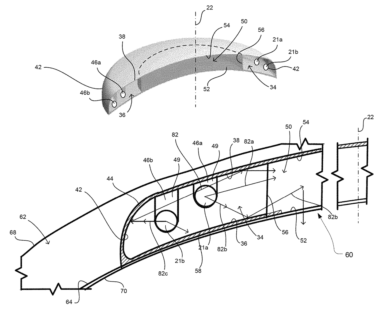
[0037]A device according to one embodiment of the invention incorporates a first optically dispersive element in the form of a radially dispersive optical fiber 20 (FIG. 1). As used in this disclosure, the term “optically dispersive element” refers to an element that is adapted to scatter light propagating in a direction of propagation so that an appreciable portion of such light is redirected in directions transverse to the direction of propagation. The term “dispersive” is used herein interchangeably with the term “scattering”, and has the same meaning as discussed in the foregoing sentence. The term “radially dispersive optical fiber” refers to a fiber, such as fiber 20, which is adapted to allow propagation of light along the length of the fiber while also scattering an appreciable portion of the light propagating along the fiber in directions transverse to the length of the fiber.

[0038]The degree of dispersion in an optical fiber can be stated in terms of its “extinction length...


PUM


Abstract

A device and method for applying light to the cornea of the eye as, for example, to promote crosslinking of collagen in the cornea for vision correction. The device may include a structure having form and size similar to a conventional contact lens. The structure may include an optically dispersive element such as a mass of an optically dispersive material that may be contained in a cavity of a reflective element. Light applied to the dispersive mass as, for example, by an optical fiber connected to the structure is dispersed in the structure and passes into the cornea. The patient may blink or close the eye during the procedure, which increases patient comfort and aids in maintaining hydration of the cornea.

Description

CROSS-REFERENCE TO RELATED APPLICATIONS[0001]The present application claims the benefit of the filing date of U.S. Provisional Patent Application No. 61 / 839,016 filed Jun. 25, 2013, the disclosure of which is hereby incorporated herein by reference.BACKGROUND OF THE INVENTION[0002]The present application relates generally to devices for applying light such as ultraviolet (“UV”) light to the cornea of the eye; to methods of manufacturing such devices; and to methods of applying phototherapy to the eye.[0003]In humans and other mammals, the eye includes a clear, dome-shaped element referred to as the cornea disposed at the front of the eye. Light passes into the eye through the cornea and, after passing through other structures such as the iris and the lens of the eye, ultimately impinging on the retina. The light impinging on the retina is converted to neural impulses that are processed to form the visual images. The cornea and the lens refract the light passing through them. In a he...

Claims


Application Information

Patent Timeline
Patent Type & Authority Patents(United States)
IPC IPC(8): A61N5/06G02C7/04A61B18/20A61F9/007A61F9/01A61F9/00A61F9/008A61F9/009
CPCA61F9/0079A61F9/009A61F2009/00872G02C7/04A61N2005/0648A61N2005/0651A61N2005/0661A61N2005/063
Inventor COOPER, FRANK GEORGELOPATH, PATRICK DAVIDACKER, DAVID E.GERSHAW, DAVID L.
Owner TECLENS
Learn More