Blood pressure information measurement device cuff and blood pressure information measurement device provided therewith

a technology of blood pressure information and measurement device, which is applied in the field of blood pressure information measurement device cuff and blood pressure information measurement device provided therewith, can solve the problems of difficult to recreate a predetermined tightening state of the cuff and difficult to measure the blood pressure information in an accurate and stable manner

Active Publication Date: 2018-02-27
OMRON HEALTHCARE CO LTD
View PDF9 Cites 0 Cited by
  • Summary
  • Abstract
  • Description
  • Claims
  • Application Information

AI Technical Summary

Benefits of technology

[0010]One or more embodiments of the present invention provide a blood pressure information measurement device cuff that, when fitted to a measurement area, can repeatedly and easily recreate the same fitted state, and a blood pressure information measurement device including such a cuff.
[0021]According to one or more embodiments of the present invention, it is possible to achieve a blood pressure information measurement device cuff capable of repeatedly recreating the same fitted state with ease when the cuff is fitted to a measurement area, and a blood pressure information measurement device provided with such a cuff.

Problems solved by technology

Because the rotation in the circumferential direction and the rotation in the direction opposite to the circumferential direction are repeated multiple times, in the case where, for example, the blood pressure value is measured on a day-to-day basis, it is difficult to recreate a predetermined tightened state for the cuff.
As a result, variations appear in the measured values obtained through day-to-day measurements, which makes it difficult to measure the blood pressure information in an accurate and stable manner.Patent Literature 1: JP H5-39504U

Method used


Image

  • Blood pressure information measurement device cuff and blood pressure information measurement device provided therewith
  • Blood pressure information measurement device cuff and blood pressure information measurement device provided therewith
  • Blood pressure information measurement device cuff and blood pressure information measurement device provided therewith

Examples


first embodiment

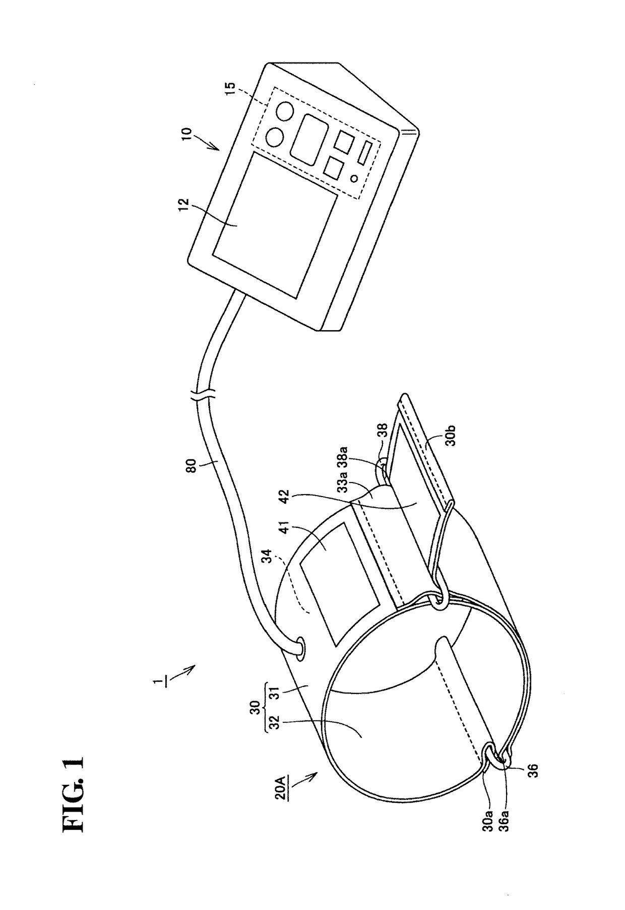
[0046]A sphygmomanometer 1 according to the present embodiment will be described with reference to FIGS. 1 through 7.

[0047]Configuration of Sphygmomanometer 1

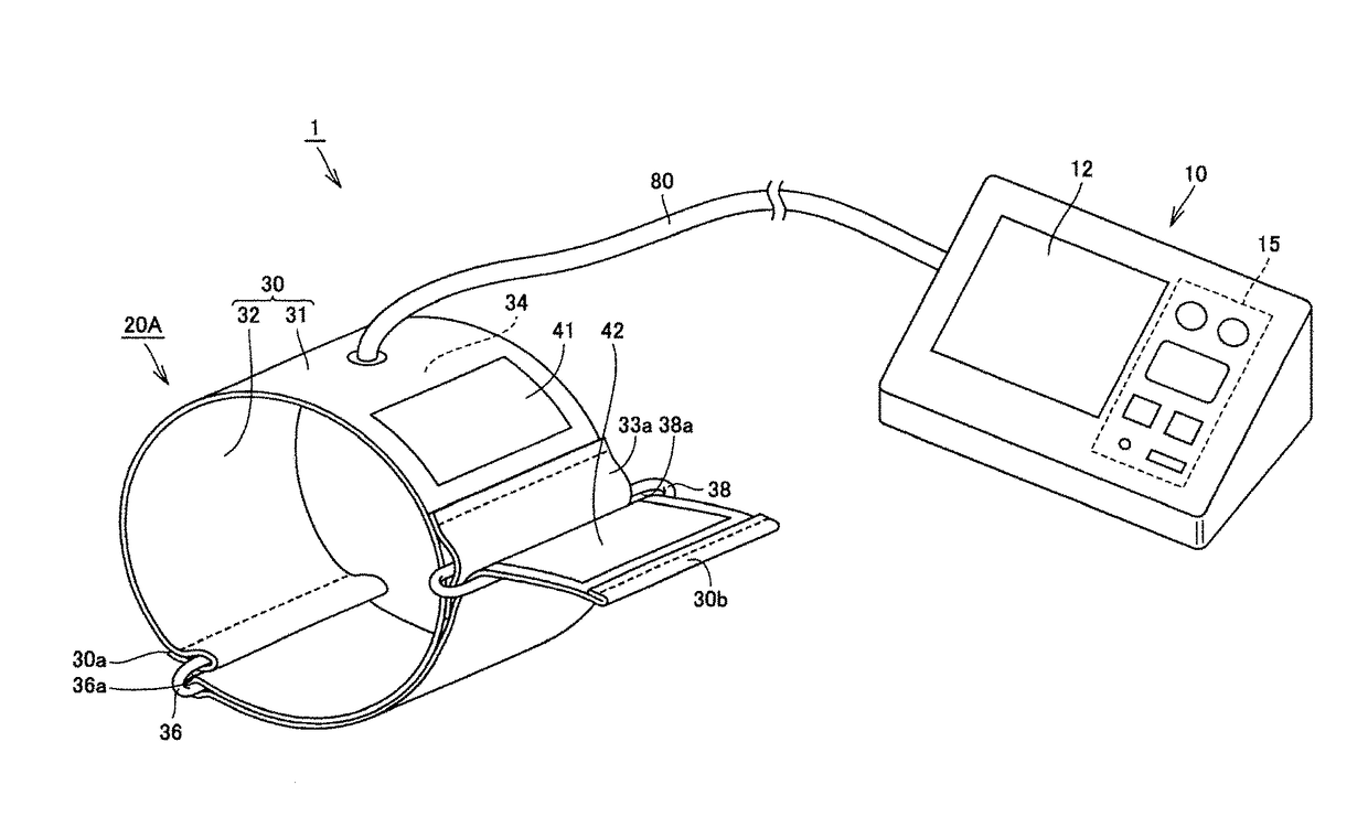
[0048]As shown in FIG. 1, the sphygmomanometer 1 includes a main body 10, a cuff 20A, and an air tube 80. The main body 10 is a box-shaped housing. A display unit 12 and an operating unit 15 are provided in the top surface of the main body 10. During measurement, the main body 10 is used by being placed on a table or the like.

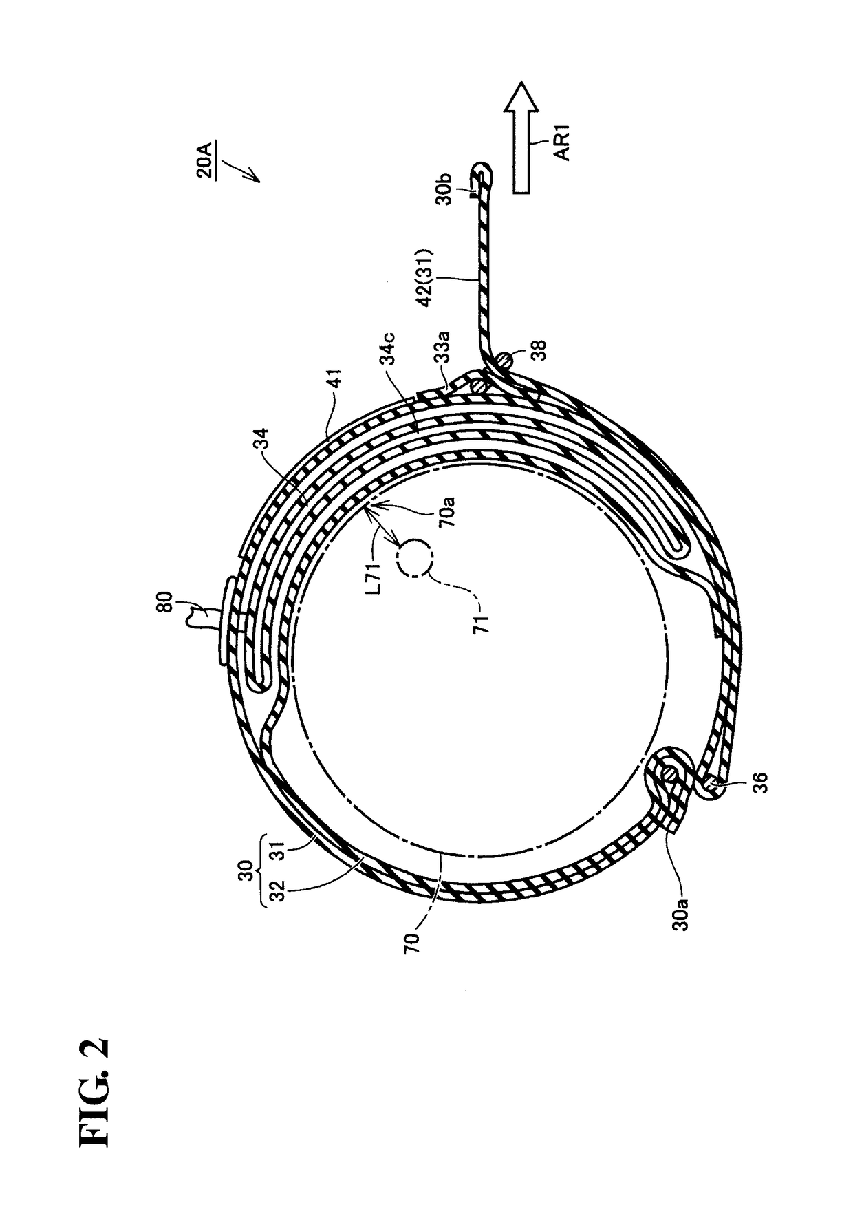
[0049]The cuff 20A includes: an outer cover 30; an air bladder 34 (see FIG. 2) that is contained within the outer cover 30 as a fluid bladder; a surface fastener 41 (fastening member); a surface fastener 42; a first loop-shaped ring 36 (first guide member); and a second loop-shaped ring 38 (second guide member).

[0050]The outer cover 30 has a front surface 31 (first main surface), a rear surface 32 (second main surface), one end portion 30a, and another end portion 30b.

[0051]The outer cover 30 is configure...

second embodiment

Variation on Second Embodiment

[0159]A sphygmomanometer according to a variation on the second embodiment will be described with reference to FIGS. 13 and 14. Here, only the differences from the second embodiment will be described.

[0160]As shown in FIG. 13, the difference between the second embodiment and the present variation lies in the other end portion 30b that is passed through the third loop-shaped ring 39 being passed through the second loop-shaped ring 38 once again after being bent back in the third loop-shaped ring 39. The other end portion 30b is passed through the insertion hole of the second loop-shaped ring 38, and is led out toward the outer side from the portion of the outer cover 30 that is formed in the circular shape.

[0161]As shown in FIG. 14, as with the cuff 20B according to the aforementioned second embodiment, the third loop-shaped ring 39 is located between the first loop-shaped ring 36 and the second loop-shaped ring 38 in the lengthwise direction of the oute...

third embodiment

[0172]A sphygmomanometer according to a third embodiment will be described with reference to FIGS. 15 and 16. Here, only the differences from the second embodiment will be described. The difference between the second embodiment and the present embodiment lies in the location where the third loop-shaped ring 39 is attached.

[0173]As shown in FIG. 16, the third loop-shaped ring 39 is located between the second loop-shaped ring 38 and the other end portion 30b of the outer cover 30 in the lengthwise direction of the outer cover 30 when the outer cover 30 is in an unrolled state.

[0174]As shown in FIG. 15, the other end portion 30b of the outer cover 30 that has been passed through the first loop-shaped ring 36 is overlaid along the outer side (the front surface 31 side) of the portion of the outer cover 30 that is formed into a circular shape. The other end portion 30b is passed through the insertion hole of the third loop-shaped ring 39.

[0175]The other end portion 30b of the outer cover...


PUM


Abstract

A blood pressure information measurement device cuff includes a fluid bladder, an outer cover, a first loop-shaped ring, and a second loop-shaped ring. The first loop-shaped ring is provided closer to one end portion of the outer cover than the position where the fluid bladder is located, and has an insertion hole for passing through and bending back another end portion of the outer cover. The second loop-shaped ring is provided on a front surface of the outer cover, and has an insertion hole for passing through the other end portion of the outer cover that has been passed through the first loop-shaped ring. According to the blood pressure information measurement device cuff, it is possible to repeatedly recreate the same fitted state with ease when the cuff is fitted to a measurement area.

Description

TECHNICAL FIELD[0001]The present invention relates to blood pressure information measurement device cuffs that are used while being worn on a measurement area when measuring blood pressure information such as a blood pressure value, and to blood pressure information measurement devices provided with such cuffs.BACKGROUND ART[0002]Blood pressure information measurement devices obtain blood pressure information of a measurement subject. The blood pressure information obtained by such blood pressure information measurement devices includes various types of information related to the circulatory system, such as a systolic blood pressure value (a maximum blood pressure value), a diastolic blood pressure value (a minimum blood pressure value), an average blood pressure value, a sphygmogram, pulse, AI (Augmentation Index) value, and the like of the measurement subject, and so on. Stress on the heart, changes in the hardness of arteries, or the like can be understood based on this blood pre...

Claims


Application Information

Patent Timeline
Patent Type & Authority Patents(United States)
IPC IPC(8): A61B5/02A61B5/022
CPCA61B5/02233
Inventor FUJITA, REIJISANO, YOSHIHIKOTANIGUCHI, MINORU
Owner OMRON HEALTHCARE CO LTD
Why Eureka
Try Eureka