Method for monitoring a thrust fault of an aircraft turbofan

a technology of turbofan and thrust fault, which is applied in the direction of process and machine control, apparatus for force/torque/work measurement, instruments, etc., can solve problems such as delay in actuation

Active Publication Date: 2018-02-20
SN DETUDE & DE CONSTR DE MOTEURS DAVIATION S N E C M A
View PDF6 Cites 4 Cited by
  • Summary
  • Abstract
  • Description
  • Claims
  • Application Information

AI Technical Summary

Benefits of technology

[0018]Preferably, the filtering function is initialised when the turbojet engine is started. Equally preferably, the filtering function is initialised depending on the sign of the thrust difference. This type of initialisation allows the risk of false alarms during monitoring of a thrust fault to be limited.
[0019]Preferably, during the initialisation, the prior modelled thrust is equal to the effective thrust of the turbojet engine. In this way, a rapid convergence of the transient-phase model is obtained in order to obtain the most relevant time constant at the given iteration.
[0022]The monitoring method thus allows indirect detection of whether the thrust setting of the turbojet engine is defined by the throttle control lever setting or by the idle speed value. This indirect detection of idling, which is not related to the idle-speed regulating device, allows the reliability of the monitoring to be increased by avoiding the use of common modes.
[0026]Preferably, a penalty parameter is applied to said alarm threshold which depends on the criticality of the auxiliary condition being monitored. Thus, if a critical auxiliary condition is in an abnormal state, the alarm threshold is designed to be triggered by the slightest thrust difference. By forming a hierarchy of auxiliary conditions, the alarm threshold is defined in a relevant way, thereby limiting the risk of false alarms while increasing the sensitivity of the monitoring.

Problems solved by technology

During this transient phase, because the latency time may vary, detecting a thrust fault is impossible, which delays the actuation of the UHT (uncontrolled high thrust) and ATTCS (automatic take-off thrust control system) safety systems and is a drawback.

Method used


Image

  • Method for monitoring a thrust fault of an aircraft turbofan
  • Method for monitoring a thrust fault of an aircraft turbofan
  • Method for monitoring a thrust fault of an aircraft turbofan

Examples


Embodiment Construction

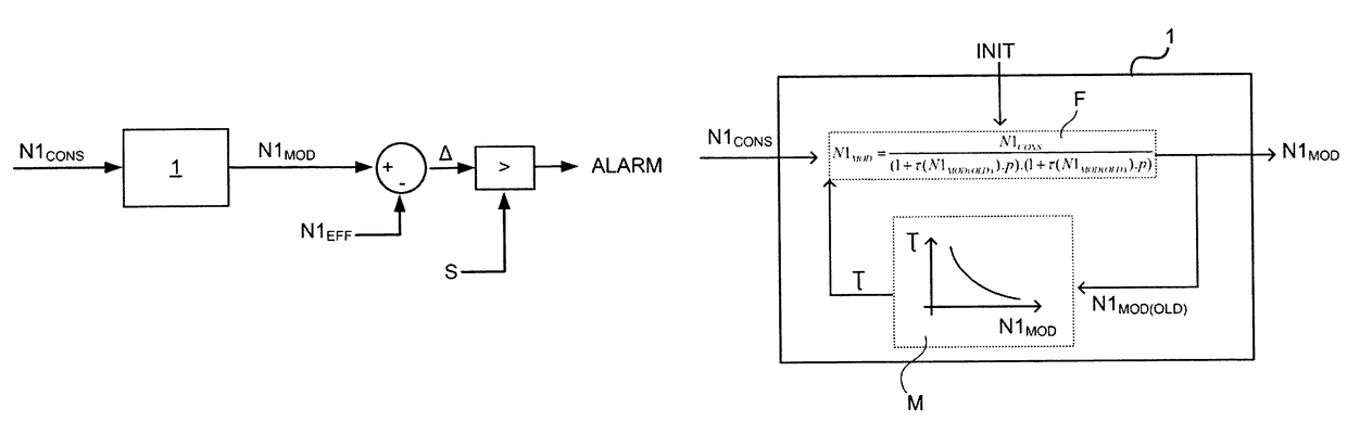
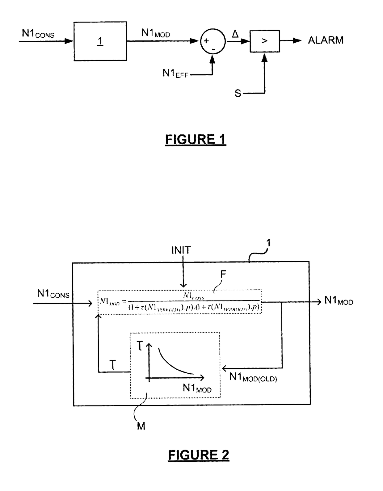
[0037]FIG. 1 is a schematic illustration of a method according to the invention for monitoring a thrust fault of an aircraft turbojet engine by means of an on-board computer of said aircraft when modifying the thrust setting of said turbojet engine.

[0038]The invention will be described for a dual-spool turbojet engine comprising a low-pressure spool and a high-pressure spool. For the sake of clarity, the speed of rotation of the low-pressure spool, also referred to as “speed N1”, will be used to determine the thrust of the turbojet engine. It is self-evident that other parameters of the turbojet engine which depend on the thrust could also be used, in particular, the parameter EPR (engine pressure ratio).

[0039]The thrust setting N1CONS corresponds in this example to the set speed of the low-pressure spool. Preferably, the thrust setting N1CONS is defined by the pilot of the aircraft, on which the turbojet engine is mounted, using a throttle control lever.

[0040]Advantageously, the th...


PUM

PropertyMeasurementUnit
thrustaaaaaaaaaa
alarm thresholdaaaaaaaaaa
time constantaaaaaaaaaa

Abstract

A method for monitoring a thrust fault of a turbofan during a modification of the thrust setting of the turbofan, the method including a step of processing the thrust setting via a filtering function and a transient-phase model such as to obtain a modelled thrust, a step of comparing the modelled thrust to the actual thrust such as to determine a thrust difference, a step of comparing the thrust difference to an alarm threshold; and a step of emitting an alarm in the event of exceeding the alarm threshold, wherein at a given iteration, in which the prior modelled thrust is known, the transient-phase model provides a time constant in accordance with the prior modelled thrust, and the filtering function provides a modelled thrust in accordance with the time constant obtained, the prior modelled thrust and the thrust setting.

Description

GENERAL TECHNICAL FIELD AND PRIOR ART[0001]The present invention relates to the field of monitoring the thrust of a turbine engine, in particular, a turbojet engine for the propulsion of an aircraft.[0002]Conventionally, an aircraft is propelled by at least two turbojet engines which are mounted respectively on the two wings of the aircraft. To control the thrust of turbojet engines, the pilot of the aircraft conventionally actuates a throttle control lever for each turbojet engine.[0003]The thrust of each turbojet engine is conventionally monitored so as to ensure that the actual thrust of the turbojet engine conforms to the thrust setting chosen by the pilot of the aircraft using the throttle control lever. The effective thrust of a turbojet engine can only be measured indirectly for a turbojet engine. In practice, for a twin-spool turbojet engine comprising a low-pressure spool and a high-pressure spool, monitoring the speed of rotation of the low-pressure spool, also known as “s...

Claims


Application Information

Patent Timeline
Patent Type & Authority Patents(United States)
IPC IPC(8): F01D21/00F02C9/28G05B17/02G01M15/14G01L5/13
CPCG01M15/14F01D21/003F02C9/28G01L5/133G05B17/02F05D2270/44F05D2260/80F05D2260/81F05D2260/821F05D2270/335F02C9/00B64D31/00
Inventor DJELASSI, CEDRIK
Owner SN DETUDE & DE CONSTR DE MOTEURS DAVIATION S N E C M A
Why Eureka
Try Eureka