
External discharge hall thruster

a hall thruster and external discharge technology, applied in the field of space vehicle engines, can solve the problems of short life, erosion of hall thrusters, and difficulty in scaling down these devices to low power levels, and achieve the effects of reducing the need for very expensive, reducing the dry mass/volume of the overall propulsion system, and facilitating the modeling of thruster plume and spacecraft interaction

Active Publication Date: 2018-02-20
KARADAG BURAK
View PDF1 Cites 1 Cited by
  • Summary
  • Abstract
  • Description
  • Claims
  • Application Information

AI Technical Summary

Benefits of technology

This design achieves a high lifetime with comparable thrust-to-power ratio and specific impulse, reduces dry mass and volume, and simplifies modeling and simulation, eliminating the need for costly lifetime tests and erosion research.

Problems solved by technology

Scaling-down these devices to low power levels is quite a challenge because of the large surface area to volume, and the physical limits to the magnetic circuit miniaturization.
Besides, scaling-down the thruster channel geometry results in short lifetime because of rapid erosion of thruster parts like discharge channel and magnetic pole piece, caused by increased plasma-wall interactions.
Power loss to the channel walls is the main power / efficiency loss source, and cause of erosion in conventional Hall thrusters.

Method used


Image

  • External discharge hall thruster
  • External discharge hall thruster
  • External discharge hall thruster

Examples


Embodiment Construction

[0016]In Hall thrusters, magnetic field generated by a set of coils and pole pieces traps and inserts electrons into spiral orbits. The entrapped electrons ionize the neutrals through collisions and gradually diffuse from the cathode to anode maintaining a strong axial electric field throughout the discharge channel. Axial electric field crossed with the radial magnetic field forces the electrons to drift azimuthally enabling quasi-neutral plasma acceleration and thrust generation. The problem in this process is that erosion of the channel walls and pole pieces that protect the magnetic circuit due to ion impingement leads to failure of the thruster. My invention describes a Hall thruster overcoming erosion problem by having both ionization and acceleration regions entirely in free space rather than a cavity. In addition to the channel walls, heavy magnetic core, pole pieces, electromagnetic coils and related power supplies are also eliminated through use of permanent magnets for a ...


PUM


Abstract

The invention is a Hall thruster that does not have any discharge channel, and magnetic pole piece. The Hall thruster utilizes permanent magnets to produce magnetic field with strong radial component in front of an annular anode, and expands propellant directly into vacuum through the anode acting also as a gas distributor. The invention reduces mass and complexity of conventional Hall thrusters, and offers a radical solution to discharge channel and magnetic pole piece erosion problem.

Description

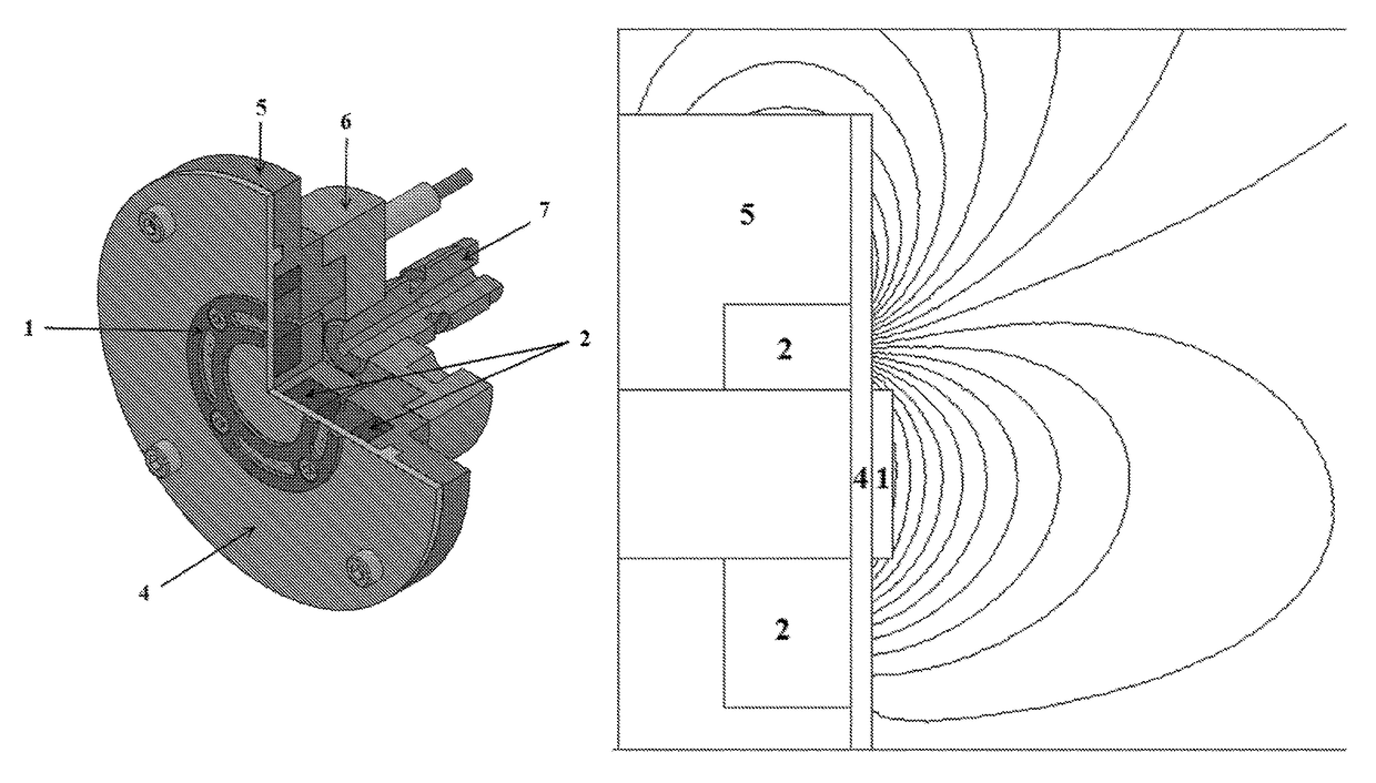
CROSS REFERENCE TO RELATED APPLICATIONS[0001]This application claims priority from U.S. Provisional Application Ser. No. 62 / 277,992 filed Jan. 13, 2016, the disclosure of which is incorporated herein.FIELD OF THE INVENTION[0002]The present invention relates to space vehicle engines in general, and to Hall thrusters in particular.BRIEF DESCRIPTION OF THE DRAWINGS[0003]Features of the present invention can be better understood with reference to the drawings described below. The drawings are not necessarily to scale; emphasis instead generally being placed upon illustrating the principles of the invention.[0004]FIG. 1 illustrates a cutaway view of a preferred embodiment of the present invention.[0005]FIG. 2 schematically illustrates a magnetic field configuration calculated for a preferred embodiment of the invention.[0006]FIG. 3 illustrates a cutaway view of another preferred embodiment of the present invention.[0007]FIG. 4 schematically illustrates a magnetic field configuration calc...

Claims


Application Information

Patent Timeline
Patent Type & Authority Patents(United States)
IPC IPC(8): F03H1/00B64G1/40H01J27/14
CPCF03H1/0075B64G1/405F03H1/0012H01J27/146F03H1/0068H01J27/143F03H1/0062B64G1/413
Inventor KARADAG, BURAK
Owner KARADAG BURAK
Learn More