Fire sprinkler with improved protective shell

a protective shell and fire sprinkler technology, applied in fire rescue and other directions, can solve the problems of insufficient mounting stability and robustness of the protective shell with limited contact area between the protective shell and the opposing bars of the frame, and easy shake of the protective shell

Active Publication Date: 2018-02-20
PROTECTOR SAFETY IND LTD
View PDF8 Cites 0 Cited by
  • Summary
  • Abstract
  • Description
  • Claims
  • Application Information

AI Technical Summary

Benefits of technology

[0006]In view of the foregoing, one object of the present invention is to provide a fire sprinkler that can solve the problem of the inadequate robustness of a mounting between the protective shell and the valve body.
[0008]According to one feature of the embodiments of the present invention, in mounting the fire sprinkler of the present invention, the protective shell can be moved linearly, rather than being moved rotationally as in the conventional devices, to adjust the height of the protective shell. This feature allows the position of the protective shell to be adjusted more quickly and conveniently as compared with the conventional one. Furthermore, through the confining function of the guide portions of the protective shell, the protective shell and the valve body can be mounted more securely, and thus the protective shell can resist vibrations or impacts from construction activity or earthquake.
[0009]More specifically, each guide portion is formed into a channel-like member that has two side walls and defines a channel therebetween. The two side walls of the channel-like member receives one of the opposing bars to confine the associated bar to moving along the channel. Each engagement portion can be formed on a bottom of the channel of the channel-like member or the two side walls of the channel-like member. Accordingly, the position of the engagement portions of the protective shell relative to the stop portions of the opposing bars can be adjusted, so that the protective shell can be mounted to the valve body at an appropriate height.
[0012]Another object of the present invention is to provide a fire sprinkler that can solve the problem of the reduced capability of the heat-activated glass bulb resulting from the provision of the protective shell.
[0013]To achieve the above object, the protective shell can be defined with at least one ventilation hole to increase the thermal transfer. The ventilation hole can have various forms, such as a circular hole, a rectangular hole, a number of elongated rectangular holes, an array of square holes and the like. The ventilation hole can speed up the heated ambient air flowing into the protective shell to allow the glass bulb therein to get broken more easily, so that the time required to break the glass bulb can be shortened, and thus the fire detection capability of the fire sprinkler can be increased.

Problems solved by technology

However, the threaded structure of the conventional fire sprinklers has the following disadvantages:1. The contact area between the protective shell and the opposing bars of the frame is limited, and thus the protective shell is easy to be shaken when it is subject to an external vibration, which may result from a construction activity or an earthquake, or the protective shell is easy to be tilted when it is touched by other pipes.
Thus, the mounting stability and robustness of the protective shell with the opposing bars of the frame is inadequate.2. Although the protective shell can provide a protection for the heat-activated glass bulb, it can cause poor ventilation within the protective shell and thus the capability of the glass bulb to detect a high temperature in a mom can be reduced.

Method used


Image

  • Fire sprinkler with improved protective shell
  • Fire sprinkler with improved protective shell
  • Fire sprinkler with improved protective shell

Examples


Embodiment Construction

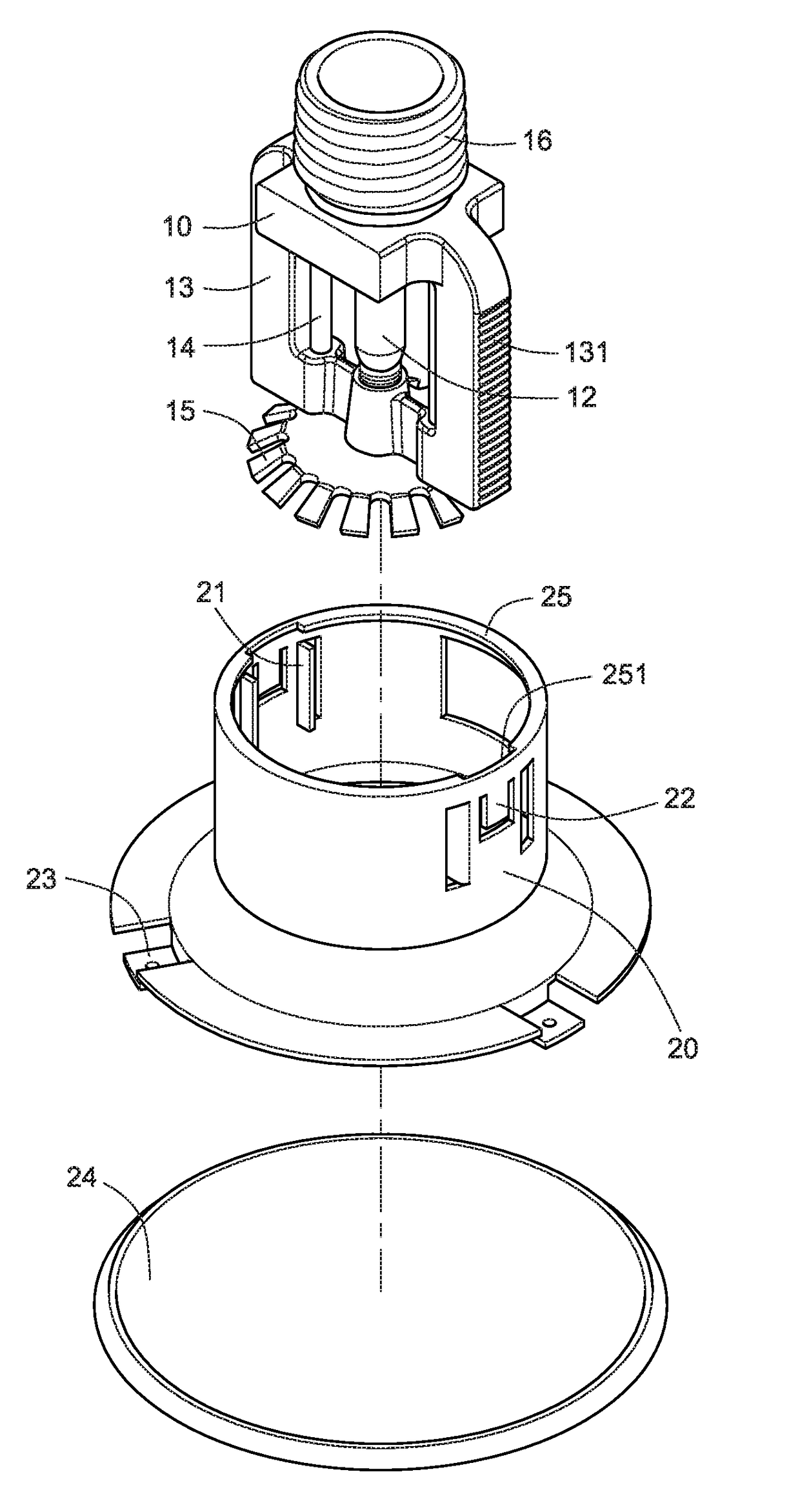
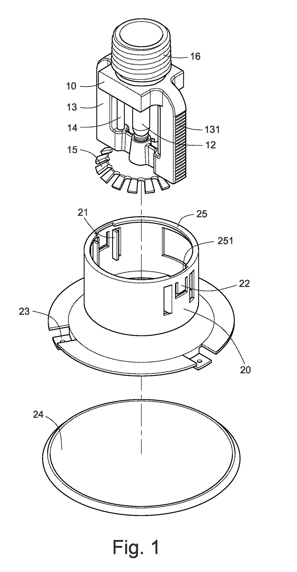
[0028]FIGS. 1 through 4 show a first embodiment of the present invention concerning a fire sprinkler, which generally comprises a valve body 10 and a protective shell 20.

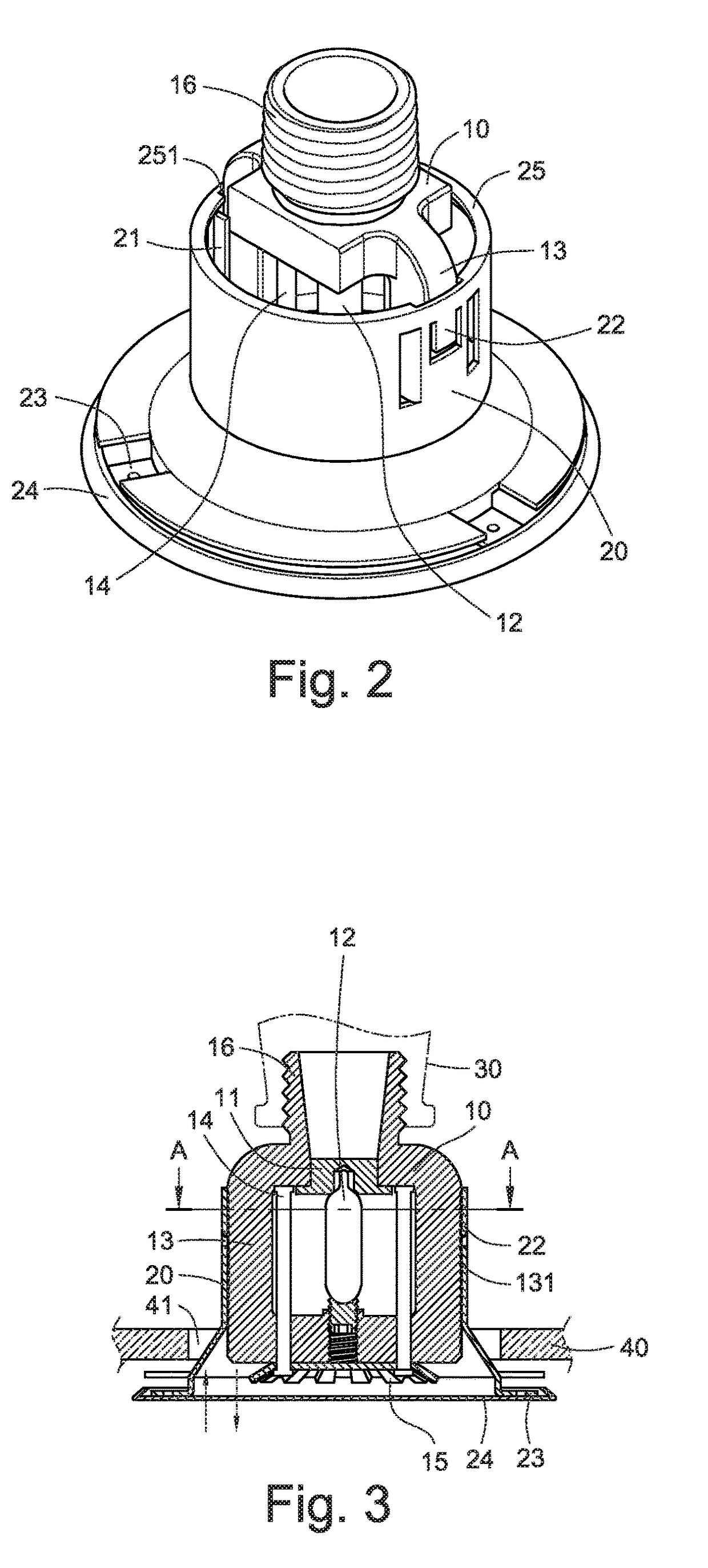
[0029]As shown in FIG. 3, the fire sprinkler is installed at a ceiling 40. For fire protection, the fire sprinkler should extend through an opening 41 of the ceiling 40. The valve body 10 is provided with a threaded portion 16 at its top, through which a water supply pipe 30 for fire protection can be connected to the fire sprinkler. Furthermore, the valve body 10 defines therein an orifice that is normally fitted with a cap 11, which is urged by a heat-activated glass bulb 12 so as to close the orifice and thus prevent water flowing from the orifice while in normal condition. The valve body 10 is provided with two opposing bars 13 extending downwardly from two sides thereof to form a frame that can support the heat-activated glass bulb 10 being located between the two opposing bars 13 and being engaged between the ...


PUM


Abstract

A fire sprinkler includes a valve body and a protective shell. The valve body defines therein an orifice being normally fitted with a cap. The valve body is provided with two opposing bars extending downwardly from two sides thereof to form a frame that supports a heat-activated glass bulb engaged between the cap and a bottom of the frame. The protective shell can be mounted to the opposing bars to surround the glass bulb. Each of the opposing bars is provided with a stop portion. The protective shell is provided with two opposing guide portions and two opposing engagement portions, wherein each guide portion of the protective shell receives one of the opposing bars to allow the engagement portions of the protective shell to be engaged with the stop portions of the opposing bars. It allows the protective shell to be mounted to the valve body more securely.

Description

TECHNICAL FIELD OF THE INVENTION[0001]The present invention relates to a fire sprinkler and, more particularly, to a fire sprinkler containing an improved protective shell.DESCRIPTION OF THE PRIOR ART[0002]As commonly known, fire sprinklers are usually installed in a building for fire protection. To detect a fire, the existing fire sprinklers employ a valve body provided with a heat-activated glass bulb that can urge against the orifice cap of the valve body. With this type of fire sprinkler, when a fire occurs, due to a high temperature, the heat-activated glass bulb can break and thus water can flow out of the orifice of the valve body to produce a water spray to extinguish the flames.[0003]Generally, the valve body employed in the conventional fire sprinklers is provided with two opposing bars that can form a frame to support the heat-activated glass bulb. Also, the valve body is mounted with a protective shell around the opposing bars of the frame of the valve body to protect th...

Claims


Application Information

Patent Timeline
Patent Type & Authority Patents(United States)
IPC IPC(8): A62C37/11A62C35/68A62C37/14
CPCA62C37/11A62C37/14A62C35/68
Inventor CHEN, JUNG-WEN
Owner PROTECTOR SAFETY IND LTD
Why Eureka
Try Eureka