Protective surgical cutter

a technology of surgical cutters and splints, applied in the direction of metal working devices, etc., can solve the problems of severe and potentially life-threatening wounds, risks to the wearer of rings,

Active Publication Date: 2018-02-13
NAT GUARD HEALTH AFFAIRS +2
View PDF6 Cites 3 Cited by
  • Summary
  • Abstract
  • Description
  • Claims
  • Application Information

AI Technical Summary

Benefits of technology

[0008]The guide includes a groove at least as wide as a width of at least one of a cutting blade of the first blade and a cutting blade of the second blade. The groove allows the guide to shield a wearer of the ring from the cutting blades as the first and second blades move along a length of the guide within the groove of the guide while exposing the ring to a clamping force of the cutting blades of the first and second blades.
[0009]Connecting the locator and the guide is a slot. The slot allows adjustment of the second end of the guide within the second end of the locator to adjust a length of the guide, and a distance between the first guard and the second guard.
[0015]The stopper is adjustable along a length, allowing adjustment of the minimum distance between the end of the first guard and the end of the second guard.

Problems solved by technology

However, such apparatus and methods may pose risks to the wearer of a ring, particularly the risk of getting cut or injured during ring removal, in some cases resulting in severe and potentially life threatening wounds.

Method used


Image

  • Protective surgical cutter
  • Protective surgical cutter
  • Protective surgical cutter

Examples


Embodiment Construction

[0038]In the drawings, like reference numerals designate identical or corresponding parts throughout the several views. Further, as used herein, the words “a”, “an” and the like generally carry a meaning of “one or more”, unless stated otherwise. Referring now to the drawings, like reference numerals designate identical or corresponding parts throughout the several views.

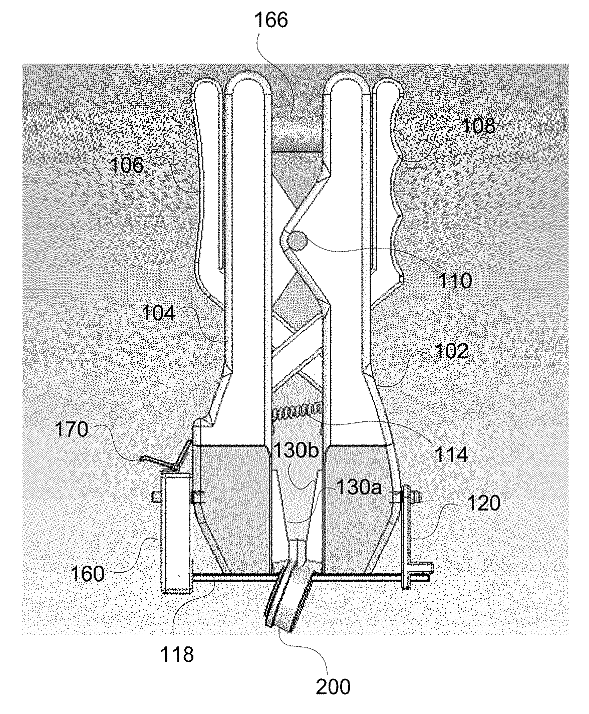
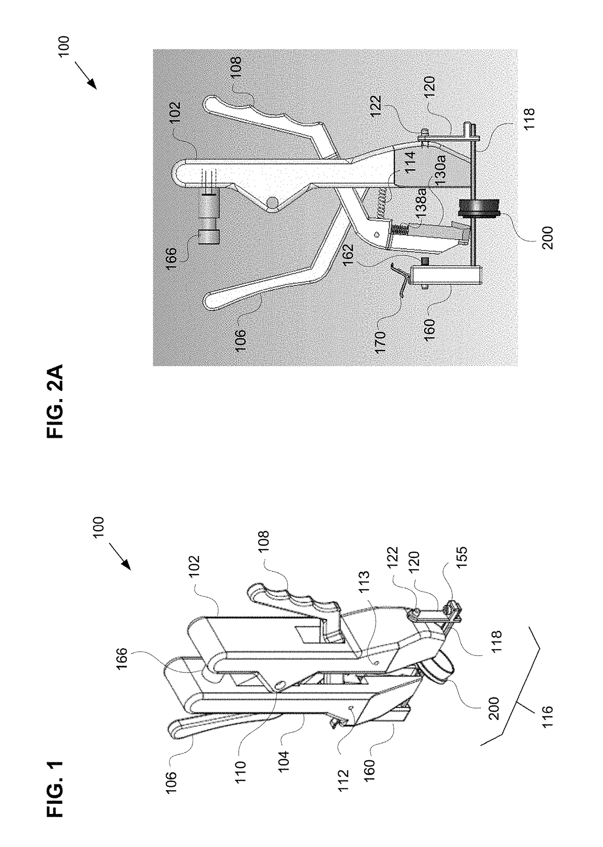
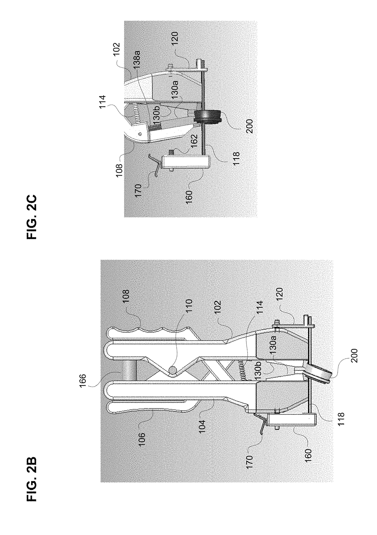
[0039]FIG. 1 is a perspective view of a surgical cutting tool 100 in a neutral position, according to one example. The surgical cutting tool 100 comprises a guard 102 rotatably connected to a guard 104 about a guard joint 110. The guard joint 110 is comprised of a guard joint 110a of the guard 104, and guard joints 110b, 110c of the guard 102.

[0040]A handle 106 is rotatably connected to the guard 102 about a handle joint 113, and a first portion of the handle 106 is partially disposed within the guard 102 when the surgical cutting tool 100 is in a neutral position. The handle joint 113 is comprised of a handle joint...


PUM


Abstract

An apparatus and method are provided for surgical removal of a ring. The apparatus includes guards rotatably connected, handles rotatably connected to the guards that each include a portion partially disposed within the respective guard, a guide connected to the guards, and blades disposed on the portion of the handles. The blades contact with at least one of the guide and an inner surface of the respective guard. A rotational axis of a joint between the guards, a rotational axis of a first handle and a first guard, and a rotational axis of a second handle and a second guard are substantially parallel. Movement of a first end of the first handle toward a first end of the second handle results in movement of a second end of the first handle toward a second end of the second handle, and movement of a first blade toward a second blade.

Description

BACKGROUNDField of the Disclosure[0001]The present disclosure is directed toward an apparatus and method for removing a ring worn on a body.Description of the Related Art[0002]Removal of a ring worn on a finger, toe, or other body part may be necessary at times. However, under certain circumstances the ring may not be removed by simply sliding it off the body due to, for example, swelling or injury of the body, or deformation of the ring itself. In such situations, the ring may need to be removed with the use of an apparatus or method other than sliding the ring off the body.[0003]However, such apparatus and methods may pose risks to the wearer of a ring, particularly the risk of getting cut or injured during ring removal, in some cases resulting in severe and potentially life threatening wounds.[0004]For this reason it is important that improved methods and apparatuses for the safe removal of rings from the body continue to be developed with the aim of reducing the frequency and se...

Claims


Application Information

Patent Timeline
Patent Type & Authority Patents(United States)
IPC IPC(8): B26B13/00B26B11/00B26B29/06B26B17/00
CPCB26B17/00B26B29/06B26B13/00B26B11/00
Inventor AL MODHEN, FAYEZ
Owner NAT GUARD HEALTH AFFAIRS
Why Eureka
Try Eureka