
Plasma resection electrode

a plasma resection and electrode technology, applied in the field of electrosurgical instruments, can solve the problems of undesired tissue heating, undesired tissue heating, coagulation or evaporation at the contact point with the patient, etc., and achieve the effects of increasing the probe efficiency, reducing the applied rf power, and high power density

Active Publication Date: 2018-02-13
COOK MEDICAL TECH LLC +1
View PDF183 Cites 5 Cited by
  • Summary
  • Abstract
  • Description
  • Claims
  • Application Information

AI Technical Summary

Benefits of technology

[0019]In the context of the present invention, the floating electrode generates and concentrates high power density in the vicinity of the active region, and results in more efficient liquid heating, steam bubble formation, bubble trapping and arc formation in this region. This increases the probe efficiency, which, in turn, allows the surgeon to substantially decrease the applied RF power and thereby reduce the likelihood of patient burns and unintended local tissue injury. The probe may be operated so that the portion of the floating electrode in close proximity to the active electrode has sufficient current density to produce vaporization of the liquid and arcing so as to vaporize tissue. Alternatively, the probe may be operated so that the floating electrode contacts tissue, wherein those portions of the floating electrode in contact with the tissue have sufficient current density to thermally coagulate blood vessels and tissue. This is particularly useful for achieving hemostasis in vascular tissue.
[0020]The innovative electrosurgical devices with floating electrodes of the present invention may be very effective in other medical procedures, other than those involving tissue evaporation (ablation), including, for instance, for thermal tissue treatment, lesion formation, tissue sculpting, and coagulation.
[0086]whereby braze bonding of said metal active electrode and said metal floating electrode to said ceramic insulator is facilitated.
[0103]a dielectric shield disposed over a first portion of said active electrode and a second portion of said conductive member, said dielectric shield having a melting point high enough to prevent the dielectric shield from melting when the active electrode is energized.
[0109]a dielectric shield disposed over a first portion of said conductive member, said dielectric shield having a melting point high enough to prevent the dielectric shield from melting when the active electrode is energized.

Problems solved by technology

Even though the benefits are well recognized, current electrosurgical instruments and procedures suffer from very significant deficiencies.
Thus, in that monopolar devices require current to flow from the active electrode through the patient's body, they invariably allow for the possibility that some of the current will flow through undefined paths in the patient's body, particularly when the instrument is not properly designed and positioned.
Bipolar electrosurgical devices have their own inherent drawbacks, often resulting from the close orientation of the return and active electrodes.
The return electrode necessarily has a small area and, as a result, can cause undesired tissue heating, coagulating or evaporation at its contact point with the patient's tissue due to the relatively high current densities present thereon.
In addition, with the bipolar configuration, the close proximity of the active and return electrodes creates the danger that the current will short across the electrodes.
Operation at relatively low voltage, as is necessary with bipolar instruments, can lead to less efficient sparking, reduced efficiency of the instrument, undesirable overheating of nearby tissue, and longer procedure time.
Moreover, the use of electrosurgical bipolar procedures in electrically conductive environments is inherently problematic.
The presence of saline, which is a highly conductive electrolyte, can also cause electrical shorting of a bipolar electrosurgical probe, thereby causing probe destruction and unintended and unnecessary heating in the treatment environment which, in turn, can result in unintended and uncontrolled tissue destruction.
In addition, current monopolar and bipolar instruments used to cut or vaporize tissue often do not have effective means for controlling bubbles, which is essential to the safety and efficiency of many procedures.
As a result, the efficiency of the instruments is often low and the procedure length is increased.
Electro surgical instruments that lack an effective means for trapping of bubbles include, for example, cutting loops, rollers, needles and knives, resection instruments and ablators.
Furthermore, many current monopolar and bipolar instruments are not designed to take full advantage of either the electrical properties of the fluids present in the vicinity of the procedure site (bodily fluids, including blood, as well as irrigation fluids, either electrically conductive or non-conductive) or the electrical properties of the tissue itself.
This increases the size of the distal end of the electrode necessary to achieve a given ablative surface size, and necessitates the use of a cannula or other instrument, often with unnecessarily large lumens, an undesirable condition.
BPH is a very common problem in western society and, if left untreated, can give rise to poor quality of life, urinary infection, bladder stones or even kidney failure.
The squeezing sometimes causes urinary problems, such as difficulty urinating.
BPH may progress to the point of generating a dense capsule that blocks the flow of urine from the bladder, resulting in the inability to completely empty the bladder.
Eventually, this can lead to bladder and kidney malfunction.
This contamination may increase the local conductivity to a degree sufficient to cause significant current flow from uninsulated portions of a probe designed for use in a non-conductive irrigant.
While these bubbles generally do not support arcing, they cover portions of the exposed electrode surface, thereby insulating these portions of the surface.
Electrodes with inefficient designs will require substantially higher power levels than those with efficient designs.
While currently available electrodes are capable of achieving desired surgical effects, they are not efficient for accomplishing these tasks and may result in undesired side effects to the patient.

Method used


Image

  • Plasma resection electrode
  • Plasma resection electrode
  • Plasma resection electrode

Examples


examples

[0197]Hereinafter, the present invention is described in more detail by reference to the exemplary embodiments. However, the following examples only illustrate aspects of the invention and in no way are intended to limit the scope of the present invention. As such, embodiments similar or equivalent to those described herein can be used in the practice or testing of the present invention.

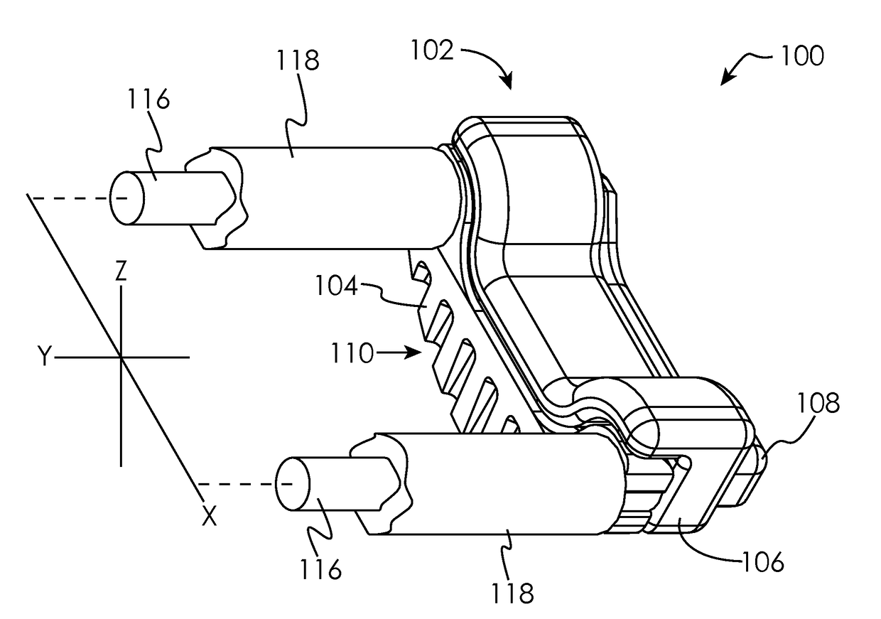
[0198]In many of the disclosed embodiments, the electrodes may be incorporated into shafts which facilitate attachment of the electrode assembly to a resectoscope. Many styles of resectoscope are known in the art, and the configuration of the shaft may be as desired in order to interface with the desired resectoscope design. The shafts further conduct power to the active electrode. The shaft may receive power through the resectoscope from any general purpose RF electrosurgical unit commonly available in operating rooms, as is known in the art.

90 Degree Tip Configuration

[0199]In one embodiment, the el...


PUM


Abstract

Disclosed herein are embodiments of an electrosurgical device that include one or more floating electrodes and are specifically adapted to remove, resect, ablate, vaporize, denaturize, coagulate and form lesions in soft tissues, preferably in combination with a resectoscope, particularly in the context of urological, gynecological, laparoscopic, arthroscopic, and ENT procedures. Specific adaptations for urological and gynecological applications, for example BPH treatment, are also described.

Description

CROSS REFERENCE TO RELATED APPLICATION[0001]This application claims the benefit of U.S. Provisional Patent Application No. 61 / 681,855, filed Aug. 10, 2012, which is hereby incorporated herein by reference in its entirety.TECHNICAL FIELD OF THE DISCLOSURE[0002]The present disclosure relates generally to the field of electrosurgery, and more particularly, to a plasma resection electrode.BACKGROUND OF THE DISCLOSURE[0003]As compared to conventional tissue removal techniques, electrosurgical procedures are advantageous in that they generally reduce patient bleeding and trauma. More recently, electro surgical devices have gained significant popularity due to their ability to accomplish outcomes with reduced patient pain and accelerated return of the patient to normal activities. Such instruments are electrically energized, typically using an RF generator operating at a frequency between 100 kHz to over 4 MHz.[0004]Many types of electrosurgical devices are currently in use. They can be di...

Claims


Application Information

Patent Timeline
Patent Type & Authority Patents(United States)
IPC IPC(8): A61B18/14A61B18/04A61B18/00A61B18/12
CPCA61B18/042A61B18/149A61B2018/1213A61B2018/122A61B2018/00101
Inventor VAN WYK, ROBERT A.CARMEL, YUVALSHKVARUNETS, ANATOLYLAVELLE, SHAYFITZGIBBON, THERESEKENNEDY, II, KENNETH C.
Owner COOK MEDICAL TECH LLC
Learn More