Electricity storage block and electricity storage module
a technology of electricity storage module and storage block, which is applied in the direction of cell components, sustainable manufacturing/processing, batteries, etc., can solve the problems of more likely lifetime-related performance degradation, and achieve the effect of reducing the compression reaction for
- Summary
- Abstract
- Description
- Claims
- Application Information
AI Technical Summary
Benefits of technology
Problems solved by technology
Method used
Image
Examples
first embodiment
—
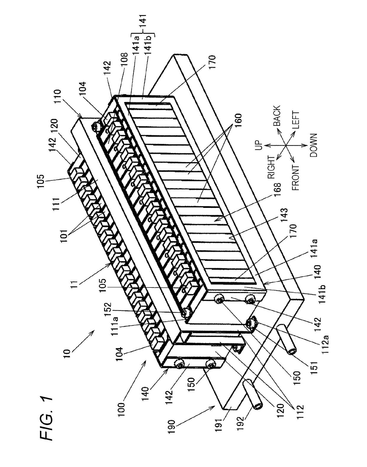
[0035]FIG. 1 is a perspective outer view of an electricity storage module 10 according to a first embodiment of the present invention. FIG. 2 is an exploded perspective view illustrating a configuration of the electricity storage module 10. The electricity storage module 10 is composed of a cooling structure 190 and an electricity storage block 100. The electricity storage block 100 includes an element stacked body 11 in which a plurality of cell batteries 101 is stacked and arranged, an integration mechanism that integrates the element stacked body 11, and a duct unit 110 as a press device that presses the element stacked body 11 toward the cooling structure 190.
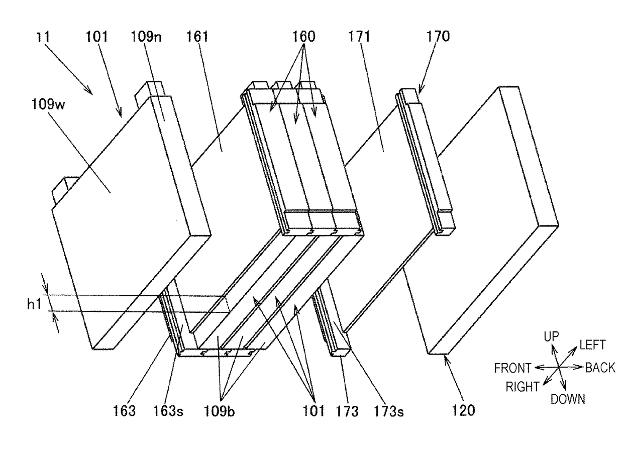
[0036]FIG. 3 is an exploded perspective view illustrating a configuration of the element stacked body 11, showing part of the element stacked body 11. As illustrated in FIG. 3, the element stacked body 11 includes the plurality of cell batteries 101 and a plurality of battery holders 160 and 170. Each of the cell batteries...
second embodiment
—
[0095]A second embodiment of the present invention will be described with reference to FIGS. 9 to 13. In these drawings, the components identical or equivalent to those in the first embodiment are given the same reference signs as those in the first embodiment and descriptions thereof are omitted. The differences from the first embodiment will be described below in detail.
[0096]FIG. 9 is similar to FIG. 3, which is an exploded perspective view illustrating a configuration of an element stacked body 21 of an electricity storage module according to the second embodiment of the present invention. FIG. 10 is a perspective view of an intermediate holder 260 constituting the element stacked body 21 illustrated in FIG. 9. FIG. 10 illustrates the intermediate holder 260 positioned at the right end of the element stacked body 21 and a part of the cell battery 101 in abutment with the intermediate holder 260 by chain double-dashed lines. FIG. 11 is a perspective view of the end holder 170.
[0...
third embodiment
—
[0112]A third embodiment of the present invention will be described with reference to FIGS. 14 to 19. In these drawings, the components identical or equivalent to those in the first embodiment are given the same reference signs as those in the first embodiment and descriptions thereof are omitted. The differences from the first embodiment will be described below in detail. FIG. 14 is an exploded perspective view illustrating a configuration of an electricity storage module 30 according to the third embodiment of the present invention. FIG. 15 is a bottom view of an electricity storage block 300 and the thermally-conductive sheet 180.
[0113]In the first embodiment, the outer surfaces of the bottom plates 109b of the cell batteries 101 serve as heat transfer surfaces attached closely to the thermally-conductive sheet 180, and the positive terminals 104 and the negative terminals 105 are provided on the cell covers 102 opposed to the bottom plates 109b (see FIG.
[0114]In contrast, in th...
PUM
| Property | Measurement | Unit |
|---|---|---|
| thick | aaaaa | aaaaa |
| thermal conductivity | aaaaa | aaaaa |
| elastic thermally-conductive | aaaaa | aaaaa |
Abstract
Description
Claims
Application Information
 - R&D
- Intellectual Property
- Life Sciences
- Materials
- Tech Scout
- Unparalleled Data Quality
- Higher Quality Content
- 60% Fewer Hallucinations
Browse by: Latest US Patents, China's latest patents, Technical Efficacy Thesaurus, Application Domain, Technology Topic, Popular Technical Reports.
© 2025 PatSnap. All rights reserved.Legal|Privacy policy|Modern Slavery Act Transparency Statement|Sitemap|About US| Contact US: help@patsnap.com


