Enveloping aerodynamic decelerator

a decelerator and aerodynamic technology, applied in the field of enveloped aerodynamic decelerators and decelerators, can solve the problems of limited size, many challenges involved, and current rigid atmospheric entry heat shields, or aeroshells,

Active Publication Date: 2018-02-06
GLOBAL AEROSPACE
View PDF15 Cites 4 Cited by
  • Summary
  • Abstract
  • Description
  • Claims
  • Application Information

AI Technical Summary

Benefits of technology

[0014]According to one aspect of the present design, there is provided an inflatable aerodynamic decelerator for use with an atmospheric entry payload. The inflatable aerodynamic decelerator comprises an inflatable envelope and an inflatant. The inflatant is configured to fill the inflatable envelope to an inflated state such that the inflatable envelope surrounds the atmospheric entry payload, causing aerodynamic forces to decelerate the atmospheric entry payload. Such a design can protect the payload from aerodynamic heating issues and simultaneously decelerate the payload during entry.
[0016]According to a third aspect of the present design, there is provided a method for causing a payload to descend at a desired rate, comprising providing an inflatable envelope and inflating the inflatable envelope to an inflated state, wherein the inflatable envelope surrounds the payload when inflated to the inflated state, causing aerodynamic forces to decelerate the atmospheric entry payload.

Problems solved by technology

A complicated aspect of space travel is the atmospheric entry phase, wherein the space system enters the atmosphere of the Earth or other planets and moons with atmospheres and can be subjected to extreme heat conditions.
Certain payloads need to enter the atmosphere and descend safely to the surface, but the challenges involved are many.
Current rigid atmospheric entry heat shields, or aeroshells, are limited by the size of the shroud (launch vehicle payload fairing).
By nature, this means that the size must be relatively small even for very large payloads.
However, temperatures and stresses are still very high and require special softgoods to withstand the environment and bulky inflation systems.
Current deployable aeroshells are very complex with many technical challenges yet to be overcome.
However, while these inflated aerodynamic decelerators can be somewhat larger in size than a rigid aerodynamic decelerator for the same payload mass and decelerator mass, they are still small enough to result in relatively high heating rates.
Because these types of inflatable aerodynamic decelerators are opaque to entry heat flux and can only radiate from the surface facing the flow, heat can build up on surfaces and create damaging temperatures.
All these complexities lead to fabric structures with relatively high areal densities (mass per unit projected area).
Current rigid atmospheric entry aeroshells thus require relatively large mass and volume for TPS and a large launch vehicle shroud for their use, which limits the entry payload capability or requires larger and expensive launch vehicles for their deployment in orbit than otherwise would be needed.
Past and current inflatable aerodynamic decelerators under research by NASA and others, which may have attitude controllability, can be stowed in smaller volumes, but still require substantial mass and volume for high-temperature TPS materials thus severely reducing payload mass capability.

Method used


Image

  • Enveloping aerodynamic decelerator
  • Enveloping aerodynamic decelerator
  • Enveloping aerodynamic decelerator

Examples


Embodiment Construction

[0037]The following description and the drawings illustrate specific embodiments sufficiently to enable those skilled in the art to practice the system and method described. Other embodiments may incorporate structural, logical, process and other changes. Examples merely typify possible variations. Individual components and functions are generally optional unless explicitly required, and the sequence of operations may vary. Portions and features of some embodiments may be included in or substituted for those of others.

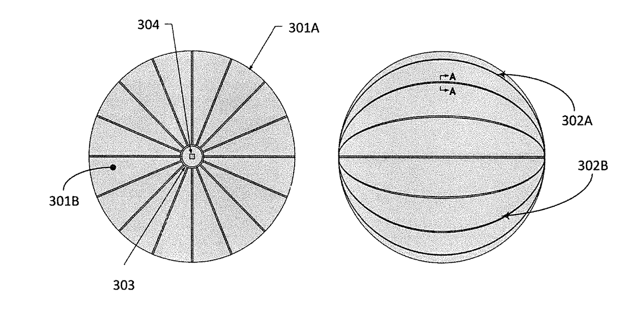
[0038]The present design provide deceleration for space systems using a very large lightweight balloon envelope design, specifically an ultra-low ballistic coefficient entry system employing materials not normally considered for atmospheric entry. This technology protects a payload from the harsh atmospheric entry environment and slows the payload so that it can land without damage.

[0039]The present ultra-low density aerodynamic decelerator design significantly reduces...


PUM


Abstract

An inflatable aerodynamic deceleration method and system is provided for use with an atmospheric entry payload. The inflatable aerodynamic decelerator includes an inflatable envelope and an inflatant, wherein the inflatant is configured to fill the inflatable envelope to an inflated state such that the inflatable envelope surrounds the atmospheric entry payload, causing aerodynamic forces to decelerate the atmospheric entry payload.

Description

[0001]This invention was made with government support under Contract No. NNX11CI01P awarded by the National Aeronautics and Space Administration (NASA) Small Business Technology Transfer (STTR) element of the Small Business Innovation Research (SBIR) Program. The government has certain rights in the invention.BACKGROUND OF THE INVENTION[0002]Field of the Invention[0003]The present invention relates generally to atmospheric entry vehicles and deceleration apparatus associated therewith, and more specifically to decelerator devices employed to slow the descent of payloads during atmospheric entry.[0004]Description of the Related Art[0005]A complicated aspect of space travel is the atmospheric entry phase, wherein the space system enters the atmosphere of the Earth or other planets and moons with atmospheres and can be subjected to extreme heat conditions. Certain payloads need to enter the atmosphere and descend safely to the surface, but the challenges involved are many. A number of ...

Claims


Application Information

Patent Timeline
Patent Type & Authority Patents(United States)
IPC IPC(8): B64G1/62B64G1/58B64G1/22
CPCB64G1/62B64G1/58B64G1/222B64G2001/224B64G1/2227
Inventor NOCK, KERRY T.AARON, KIM M.MCRONALD, ANGUS D.GATES, KRISTIN L.
Owner GLOBAL AEROSPACE
Why Eureka
Try Eureka