
Paper shredder having interchangeable feed belt cartridges

a technology of paper shredder and feed belt, which is applied in the field of paper shredder, can solve the problems of auto-feed shredder, low-priced consumer products, and wear of belts like rollers, and achieve the effect of simple mechanical linkage and simple locking mechanism

Active Publication Date: 2018-02-06
INTEK AMERICA
View PDF4 Cites 5 Cited by
  • Summary
  • Abstract
  • Description
  • Claims
  • Application Information

AI Technical Summary

Benefits of technology

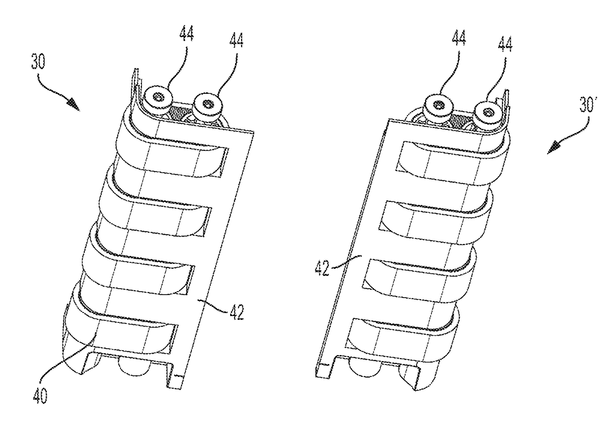
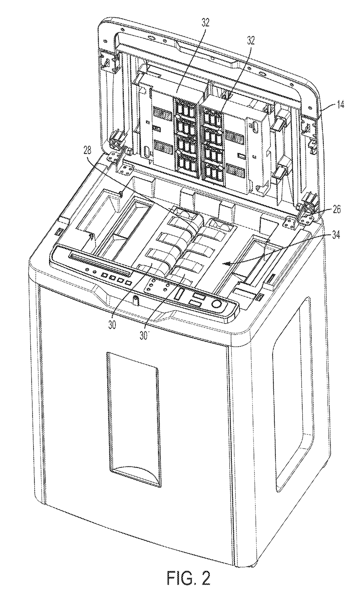
[0013]The inventor has solved his problem by encasing the belts in a frame to constitute a removable belt cartridge unit. This unit consists of a frame containing mounted drive wheels or rollers over which the belts move in a manner analogous to tracks of a military tank (armored vehicle) moving over the tank's drive wheels. The drive wheels are equipped with a simple mechanical linkage such as frictional contact or a spline linkage or other mechanical linkage so that the belts automatically connect to the drive motor of the shredder when the belt cartridge is inserted into position. A simple locking mechanism makes it easy to remove one cartridge and drop in a replacement unit. It will be appreciated that while the drawings shows four pairs of belts, a greater or lesser number of belts can be employed. The replacement cartridge can consist of all the belts in the system. Or the belts can each have their own cartridge or all the belts on one side of the feed slot can be contained in a single cartridge so that two cartridges represent a complete replacement of the belts.

Problems solved by technology

However, belts like rollers wear and eventually lose the ability reliably to grip paper.
It is possible to send a repair technician to replace the worn belts; however, the present auto-feed shredders are relatively low-priced consumer products.
The belts themselves are relatively low cost items, but the complexity of disassembling the mechanism to replace the belts is beyond the technical ability and patience of most consumers.

Method used


Image

  • Paper shredder having interchangeable feed belt cartridges
  • Paper shredder having interchangeable feed belt cartridges
  • Paper shredder having interchangeable feed belt cartridges

Examples


Embodiment Construction

[0025]The following description is provided to enable any person skilled in the art to make and use the invention and sets forth the best modes contemplated by the inventor of carrying out his invention. Various modifications, however, will remain readily apparent to those skilled in the art, since the general principles of the present invention have been defined herein specifically to provide an auto-feed paper shredder with user replaceable drive belts.

[0026]FIG. 1 shows the inventive shredder 12 which consists of a shredder component 16 which sits on top of an enclosure 18. The shredder component 16 has a lid 14 and a control panel 24 including various on and off controls. The lid 14 also has an input slot 20. Generally, the shredder component 16 is attached to the enclosure 18 by clips, screws or other mechanical fasteners although because the shredder component 16 includes a motor, it is fairly heavy and may simply rest on the enclosure 16 held in place by gravity. The enclosur...


PUM


Abstract

An auto-feed paper shredder operates by using counter-rotating belts to grasp sheets of paper from the bottom of a stack of paper and push the sheet into a shredding mechanism. Successive sheets are pulled from the stack and shredded so that an entire stack of several hundred sheets can be shredded without operator intervention. The belts that accomplish the auto-feeding are housed in roller belt assemblies that can be easily removed from and reinserted into the paper shredder. In this way when the belts become worn and no longer effectively grasp the paper, the user simply removes the assembly and inserts a new one. The worn assemblies can be returned to the manufacturer to be refurbished.

Description

CROSS-REFERENCE TO PRIOR APPLICATIONS[0001]The present application is based on and claims priority and benefit from U.S. Provisional Patent Application Ser. No. 62 / 153,991 filed on 28 Apr. 2015.U.S. GOVERNMENT SUPPORT[0002]Not ApplicableBACKGROUND OF THE INVENTION[0003]Area of the Art[0004]The present invention concerns paper shredders and more particularly a paper shredder with an auto-feed mechanism with user replaceable parts.[0005]Description of the Background of the Invention[0006]Modern paper shredders for shredding documents incorporate counter rotating shafts bearing blades and spacers so that paper passing between the blades is effectively shredded. The maximum sheet capacity of such paper shredders is dependent on the strength of the motor and the limitations of the cutting blades and rotary shafts. Although many units can handle small stacks of 10-20 sheets, when a large amount of paper must be destroyed, the user needs to stand beside the unit and continuously feed the m...

Claims


Application Information

Patent Timeline
Patent Type & Authority Patents(United States)
IPC IPC(8): B02C18/22B02C18/00
CPCB02C18/0007B02C18/2241
Inventor CHANG, HERMAN
Owner INTEK AMERICA
Learn More