
Omnidirectional sensor array system

a sensor array and omnidirectional technology, applied in the field of omnidirectional sensor array systems, can solve the problems of local image distortion, system never records or stores or manipulates the full image produced at individual sensors, and harms their practicality and effectiveness

Inactive Publication Date: 2018-01-23
ECOLE POLYTECHNIQUE FEDERALE DE LAUSANNE (EPFL)
View PDF6 Cites 9 Cited by
  • Summary
  • Abstract
  • Description
  • Claims
  • Application Information

AI Technical Summary

Benefits of technology

The present invention aims to provide an omnidirectional sensor that is simpler and more efficient than existing devices. The invention uses a combination of sensors and signal processing to create a virtual sensor with enhanced capacities. Each pixel of the virtual sensor is constructed based on light field information, optimizing the amount of computation and data flow in the system. The sensors can be attached to processing nodes that carry out a portion of the signal processing algorithms locally. This architecture is parallelized and scalable, reducing the computational load of the central processing unit. Additionally, using multiple systems and processing nodes, the location of the virtual sensor can be moved freely along any incoming directional line. Overall, the invention provides an efficient and scalable omnidirectional sensing device.

Problems solved by technology

As such, the system never records or stores or manipulates the full images produced at individual sensors.
Solutions which have been proposed so far to realize omnidirectional vision suffer from various flaws which harms their practicality and effectiveness.
Most of the proposed systems involve bulky or heterogeneous hardware, taking the form of computers or laser-based distance measurement systems prohibiting actual portability, three-dimensional mirrors which are very delicate to manipulate, may cause local image distortion due to a complex and difficult to guarantee fabrication process as well as misalignment with the imager.
This results in severe data throughput constraints in the system that make computation of these panoramas in embedded hardware difficult: the system must have enough buffer memory and computational power to access, temporarily store and manipulate all images recorded by the individual sensors composing the array.
These constrains become even more drastic for real-time video, explaining the complete lack of fully embedded real-time omnidirectional arrays in the commercial and professional camera equipment market, at present.

Method used


Image

  • Omnidirectional sensor array system
  • Omnidirectional sensor array system
  • Omnidirectional sensor array system

Examples


Embodiment Construction

[0047]The present invention will be better understood from the following detailed description and drawings which show:

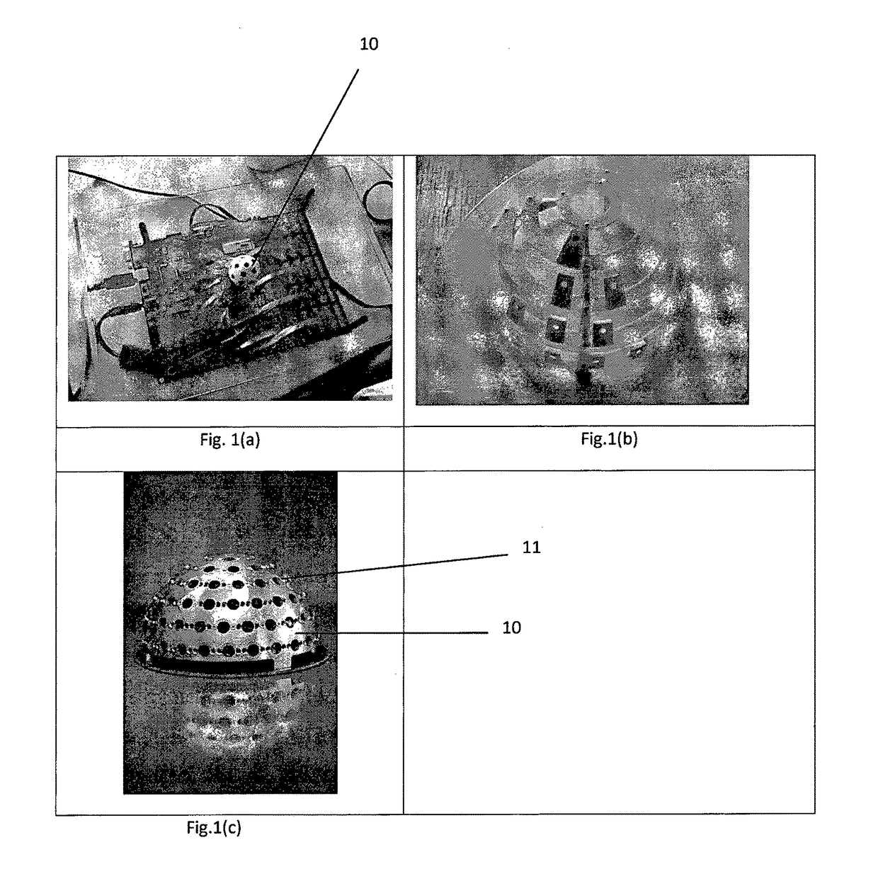
[0048]FIGS. 1a to 1c illustrate examples of a camera system according to the present invention;

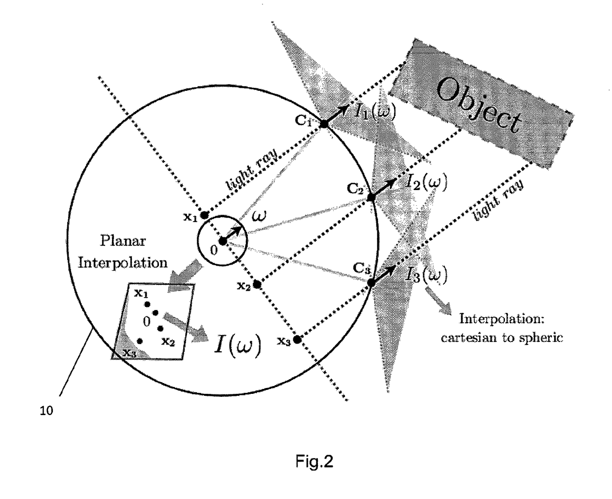
[0049]FIG. 2 illustrates the interpolation of a plenoptic function in a direction ω;

[0050]FIG. 3 illustrates a panoptic graph;

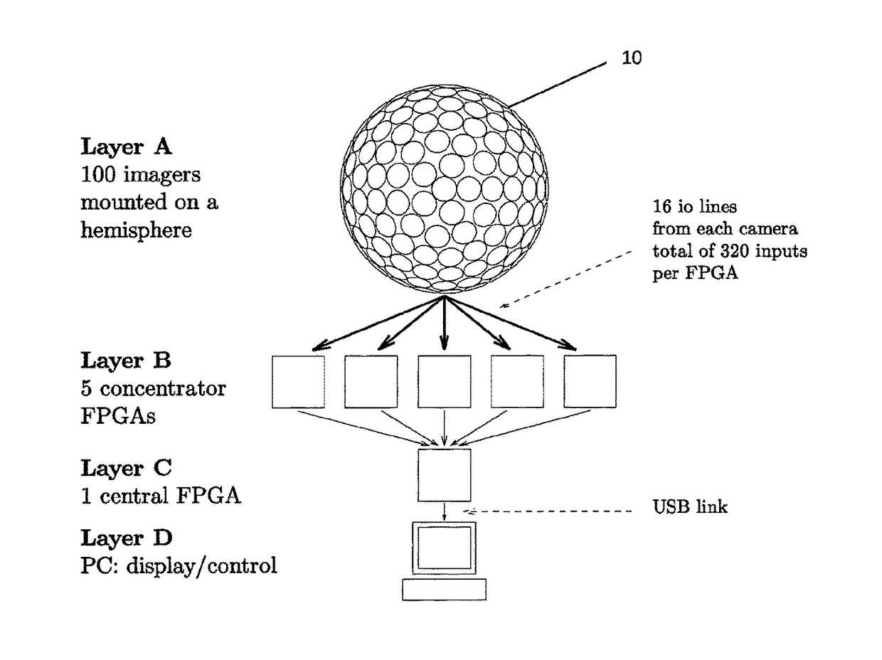
[0051]FIG. 4 illustrates an architecture of the system according to the invention;

[0052]FIGS. 5(a) and 5(b) illustrate top and side views of a hemispherical structure with seven floors;

[0053]FIGS. 6(a) and 6(b) illustrate a side view and a inner view of a panoptic camera according to the present invention;

[0054]FIG. 7 illustrates the surface of a sphere with 32 latitude and 32 longitude pixels;

[0055]FIGS. 8(a) and 8(b) illustrate a side view and a top view of a Voronoi diagram;

[0056]FIGS. 9(a) and 9(b) illustrate pinhole camera with conical field of view;

[0057]FIG. 10(a) illustrates minimum angle of view for the camera of a device with N+1 latitude f...


PUM


Abstract

An omnidirectional sensor array system, for example a panoptic camera, comprising a plurality of sensors arranged on a support of predetermined shape to acquire data, wherein said sensors are directional and wherein each sensor is attached to a processing node which comprises integrated electronics that carries out at least a portion of the signal processing algorithms locally in order to reduce the computational load of a central hardware unit.

Description

CROSS REFERENCE TO RELATED APPLICATIONS[0001]This application is a national stage application under 35 U.S.C. 371 and claims the benefit of PCT Application No. PCT / IB2011 / 054843 having an international filing date of 31 Oct. 2011, which designated the United States, and which PCT application claimed the benefit of European Patent Application No. 10189474.9 filed 29 Oct. 2010, the disclosure of which is incorporated herein by reference.FIELD OF THE INVENTION[0002]The present invention concerns an omnidirectional sensor array system, for example a panoptic camera, that can be used in many applications such as general imaging, conference cameras, security and surveillance, live broadcast, medical imaging, games, architecture measurements, navigation etc.[0003]The present invention more specifically concerns a system that implements a full-field-of-view light field camera. Contrary to traditional imagers, the system according to the present invention records and parameterize the set of ...

Claims


Application Information

Patent Timeline
Patent Type & Authority Patents(United States)
IPC IPC(8): H04N5/232H04N5/225G02B27/22G03B35/08G03B37/04
CPCH04N5/23238G02B27/2228G03B35/08H04N5/23206H04N5/2258H04N5/2259G03B37/04G02B30/34H04N23/45H04N23/58H04N23/661H04N23/698
Inventor BAGNATO, LUIGIJACQUES, LAURENTVANDERGHEYNST, PIERREAFSHARI, HOSSEINSCHMID, ALEXANDRELEBLEBICI, YUSUF
Owner ECOLE POLYTECHNIQUE FEDERALE DE LAUSANNE (EPFL)
Learn More