
Mechanism and design for addressing ram droop

a technology of rams and ram bodies, applied in the field of can bodymakers, can solve the problems of contaminated cooling fluid, fluids mixing, and fluids not completely removed by the seal assembly, and achieve the effect of shortening the ram body

Active Publication Date: 2018-01-16
STOLLE MACHINERY CO LLC
View PDF23 Cites 2 Cited by
  • Summary
  • Abstract
  • Description
  • Claims
  • Application Information

AI Technical Summary

Benefits of technology

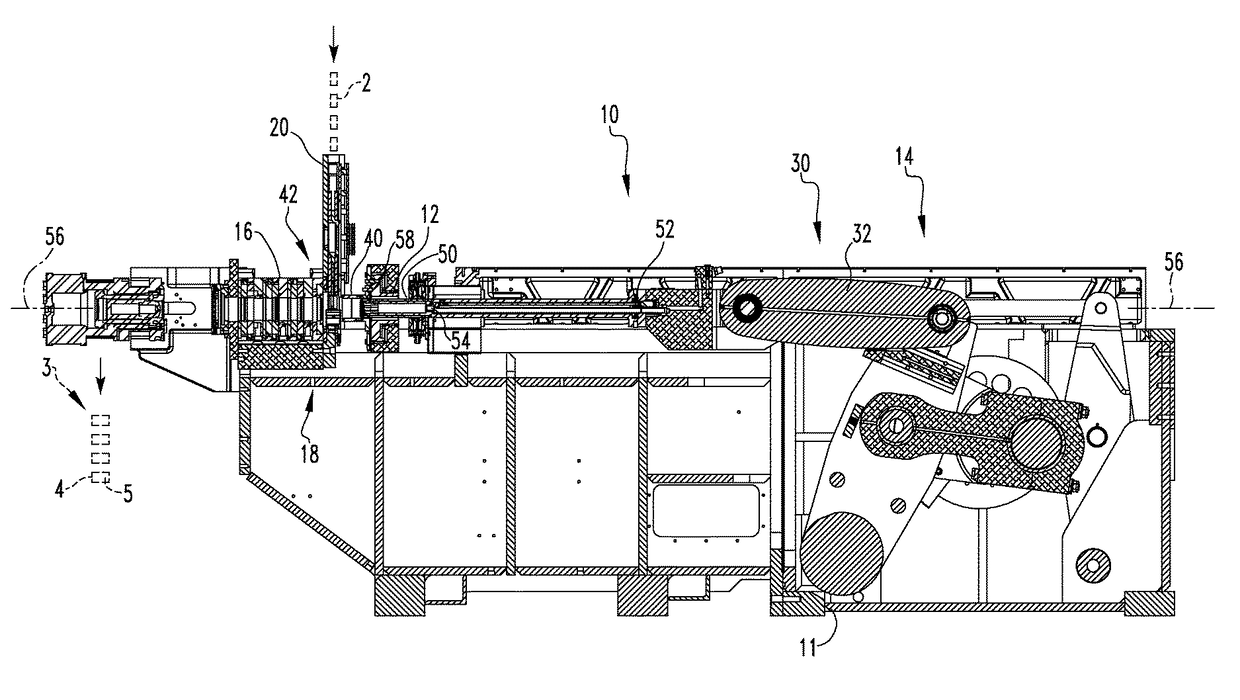
The patent describes a can bodymaker that uses a special assembly to guide and support the ram (the part that pushes the can body during the molding process). This assembly is located outside of the main part of the bodymaker, allowing for a shorter ram body and reducing the amount of material needed. This design also uses special bearings that help the ram move smoothly during the process. Overall, this design makes the bodymaker more efficient and effective at making cans.

Problems solved by technology

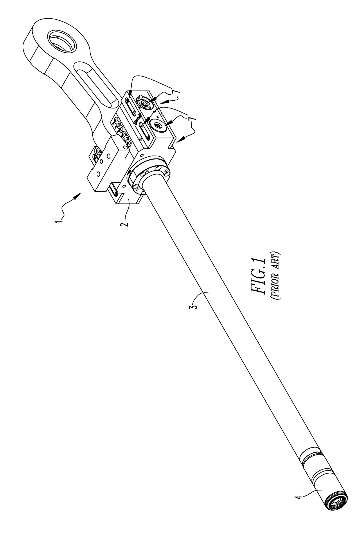
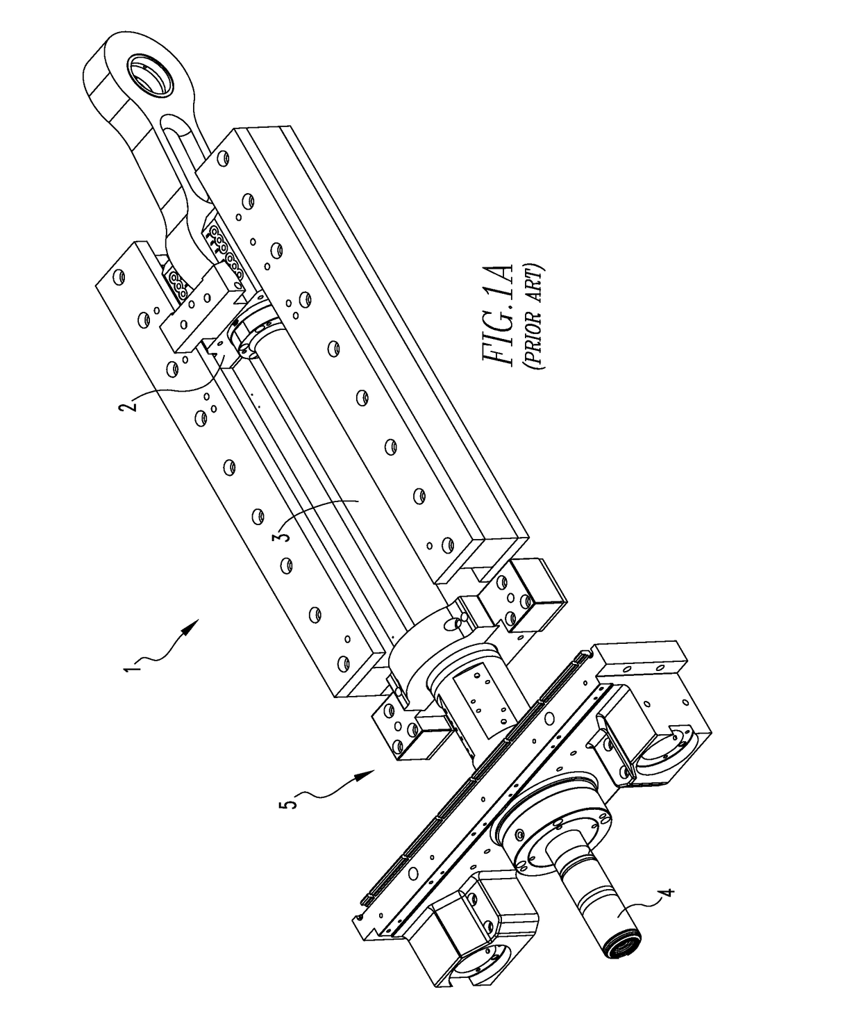
The disadvantage to this configuration is that the fluid bearing assembly fluid is not completely removed by the seal assembly.
Further, the fluids mix and the collected cooling fluid becomes contaminated.
This also means that the fluid bearing assembly fluid, which may be an expensive oil, is slowly lost.
Another disadvantage is that the ram body must have a sufficient length not only to extend through the die pack, but the seal assembly and fluid bearing assembly; for a can body of a typical 12 fluid ounce can, the ram body has a length of between about 50 inches to 52 inches when using a 24 inch stroke for a can body of a typical 12 fluid ounce can.
A ram body of any of these dimensions is prone to damage from normal wear and tear.
This narrow spacing, however, is a disadvantage, especially during the return stroke.
Ram droop is a problem on the return stroke where a can is not being formed.
In the return stroke, the punch and ram have more of a tendency to contact the tooling causing wear and damage.
That is, the length of the ram body is a stated problem,

Method used


Image

  • Mechanism and design for addressing ram droop
  • Mechanism and design for addressing ram droop
  • Mechanism and design for addressing ram droop

Examples


Embodiment Construction

[0038]Directional phrases used herein, such as, for example, clockwise, counterclockwise, left, right, top, bottom, upwards, downwards and derivatives thereof, relate to the orientation of the elements shown in the drawings and are not limiting upon the claims unless expressly recited therein.

[0039]As used herein, the singular form of “a,”“an,” and “the” include plural references unless the context clearly dictates otherwise.

[0040]As used herein, the statement that two or more parts or components are “coupled” shall mean that the parts are joined or operate together either directly or indirectly, i.e., through one or more intermediate parts or components, so long as a link occurs. As used herein, “directly coupled” means that two elements are directly in contact with each other. As used herein, “fixedly coupled” or “fixed” means that two components are coupled so as to move as one while maintaining a constant orientation relative to each other. Accordingly, when two elements are cou...


PUM

PropertyMeasurementUnit
lengthaaaaaaaaaa
lengthaaaaaaaaaa
lengthaaaaaaaaaa

Abstract

A can bodymaker ram assembly is provided. The ram assembly includes an elongated, generally hollow ram body and a tension assembly. The ram body includes a proximal end, a medial portion, and a distal end. The tension assembly includes an elongated support member. The tension assembly support member includes a proximal end and a distal end. The tension assembly support member is substantially disposed within the ram body with the tension assembly support member proximal end coupled to the ram body proximal end, and the tension assembly support member distal end coupled to one of the ram body medial portion or the ram body distal end.

Description

CROSS REFERENCE TO RELATED APPLICATION[0001]This application claims priority to U.S. Provisional Patent Application Ser. No. 61 / 870,880, filed Aug. 28, 2013 entitled MECHANISM AND DESIGN FOR ADDRESSING RAM DROOP.BACKGROUND OF THE INVENTION[0002]Field of the Invention[0003]The disclosed and claimed concept relates to a can bodymaker and, more specifically, to a can bodymaker wherein the ram assembly includes outboard bearings and a ram body having a reduced length.[0004]Background Information[0005]Generally, an aluminum can begins as a disk of aluminum, also known as a “blank,” that is punched from a sheet or coil of aluminum. That is, the sheet is fed into a dual action press where a “blank” disc is cut from the sheet by an outer slide / ram motion. An inner slide / ram then pushes the “blank” through a draw process to create a cup. The cup has a bottom and a depending sidewall. The cup is fed into one of several bodymakers, which perform a redraw and ironing operation. More specificall...

Claims


Application Information

Patent Timeline
Patent Type & Authority Patents(United States)
IPC IPC(8): B21D51/26B21D22/28
CPCB21D22/28B21D51/26B21D37/12
Inventor BUTCHER, GREGORY H.CARSTENS, AARON E.CARPER, KENNETH E.BAUER, RUSSELL
Owner STOLLE MACHINERY CO LLC
Learn More