
Array substrate and manufacturing method thereof

a technology of array substrate and manufacturing method, which is applied in the direction of electrical equipment, semiconductor devices, instruments, etc., can solve the problems of higher manufacturing cost and disadvantageous application in large-scale products, and achieve the disadvantage of large-scale products, higher manufacturing cost, and complex processing

Active Publication Date: 2018-01-09
TCL CHINA STAR OPTOELECTRONICS TECH CO LTD
View PDF12 Cites 0 Cited by
  • Summary
  • Abstract
  • Description
  • Claims
  • Application Information

AI Technical Summary

Benefits of technology

[0007]The object of the present invention is to provide an array substrate and a manufacturing method thereof which solves a technical problem existing in the conventional technology in which the processes are more complex and the manufacturing cost is higher, so that it is disadvantageous for application in large size products.
[0022]etching the gate electrodes further, so as to decrease the area of the gate electrodes covering the semiconductor layer; and
[0042]etching the gate electrodes further, so as to decrease the area of the gate electrodes covering the semiconductor layer; and
[0065]In the array substrate and the manufacturing method thereof according to the present invention, by improving the conventional manufacturing method, the manufacturing processes are simplified, and the production cost is reduced.

Problems solved by technology

The object of the present invention is to provide an array substrate and a manufacturing method thereof which solves a technical problem existing in the conventional technology in which the processes are more complex and the manufacturing cost is higher, so that it is disadvantageous for application in large size products.

Method used


Image

  • Array substrate and manufacturing method thereof
  • Array substrate and manufacturing method thereof
  • Array substrate and manufacturing method thereof

Examples


Embodiment Construction

[0081]The foregoing objects, features, and advantages adopted by the present invention can be best understood by referring to the following detailed description of the preferred embodiments and the accompanying drawings. Furthermore, the directional terms described in the present invention, such as upper, lower, front, rear, left, right, inner, outer, side, etc., are only directions with reference to the accompanying drawings, so that the used directional terms are used to describe and understand the present invention, but the present invention is not limited thereto. In the drawings, units with similar structures use the same numerals.

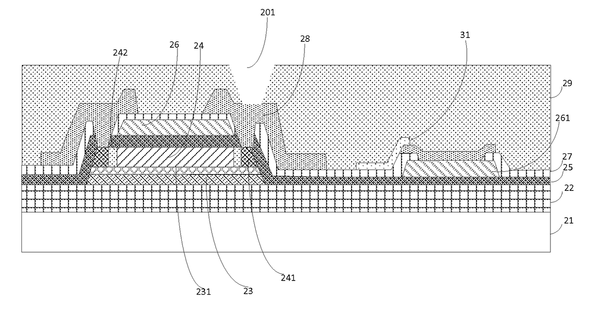
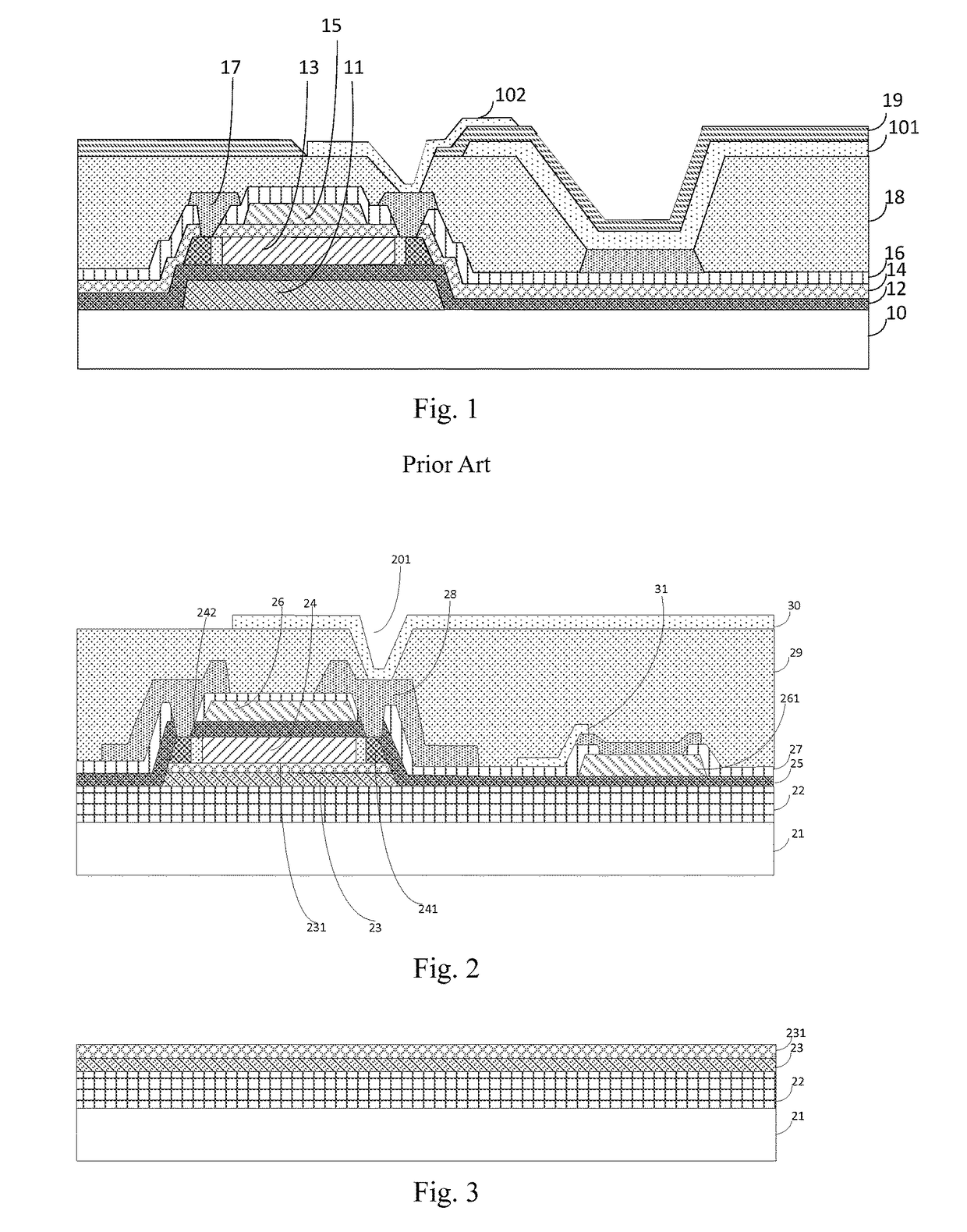
[0082]Refer now to FIG. 2, which is a structural schematic view of an array substrate according to the present invention.

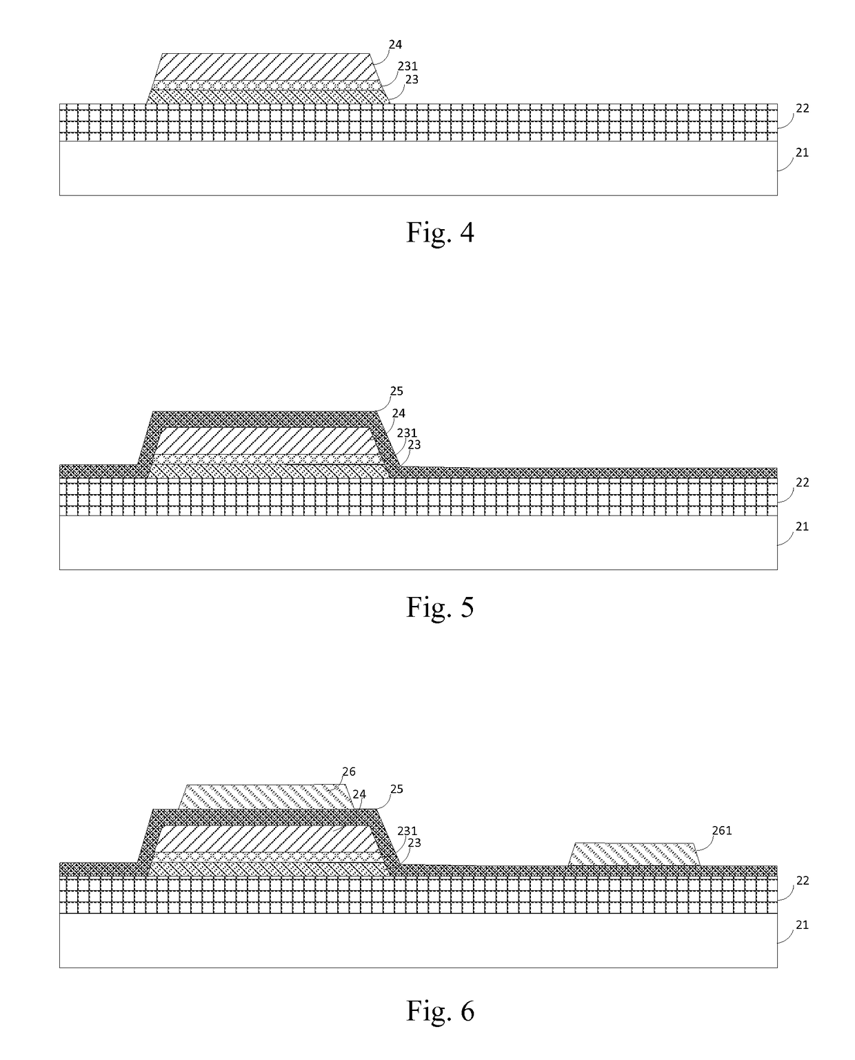
[0083]As shown in FIG. 2, an array substrate according to present invention comprises: a substrate 21, a buffer layer 22, a light-shading layer 23, a semiconductor layer 24, a first insulation layer 25, a first metal layer, a second...


PUM

PropertyMeasurementUnit
transparent conductiveaaaaaaaaaa
trigger-conductivityaaaaaaaaaa
conductivityaaaaaaaaaa

Abstract

An array substrate and a manufacturing method thereof are provided. The method has steps of: forming a buffer layer, a light-shading layer, and a whole semiconductor layer on a substrate; simultaneously patterning the semiconductor layer and the light-shading layer; and forming a first insulation layer, a first metal layer, a second insulation layer, a second metal layer, a flat layer, and a first transparent conductive layer on the patterned semiconductor layer.

Description

FIELD OF THE INVENTION[0001]The present invention relates to a technological field of liquid crystal displays, and more particularly to an array substrate and a manufacturing method thereof.BACKGROUND OF THE INVENTION[0002]Low temperature poly-silicon (LTPS) has a high electron mobility ratio, and thereby it can effectively reduce the area of thin film transistor (TFT) elements, increase the aperture ratio of pixels, and enhance the display lightness of panels, but simultaneously lowers the entire power consumption, so that the manufacturing cost of panels is substantially reduced, so now LTPS has become a research hot point in a field of liquid crystal displays.[0003]In a conventional design of LTPS, mask processes of an array substrate are more complex, generally about ten mask processes are required, so that the production capacity of the products is substantially lowered. Furthermore, since the processes are more complex, the yield rate thereof is also lower, so that LTPS is dif...

Claims


Application Information

Patent Timeline
Patent Type & Authority Patents(United States)
IPC IPC(8): H01L27/12H01L29/45H01L21/3213H01L29/66H01L29/786H01L21/02G02F1/1368H01L21/22H01L21/265
CPCH01L27/1222H01L21/02238H01L21/02532H01L21/02592H01L21/32133H01L27/124H01L27/127H01L27/1218H01L27/1288H01L29/458H01L29/66757H01L29/78633H01L29/78675H01L21/02164H01L21/26513G02F1/1368G02F2202/104H01L21/22H01L27/1214H01L27/1259H01L29/786G02F1/136209
Inventor WANG, XIAOXIAODU, PENGWANG, CONG
Owner TCL CHINA STAR OPTOELECTRONICS TECH CO LTD
Learn More