Module integrated solar position sensing device for concentration photovoltaic devices

a technology of photovoltaic devices and modules, applied in photovoltaics, solar trackers, direction finders, etc., can solve the problems of increasing deployment costs, reducing the overall performance of cpv systems, and cpv systems that require costly optics (lenses or mirrors), so as to reduce the installation and commissioning costs of cpv systems, reduce component redundancy and cost, and increase system reliability

Inactive Publication Date: 2018-01-02
RICARD PARDELL VILELLA
View PDF9 Cites 0 Cited by
  • Summary
  • Abstract
  • Description
  • Claims
  • Application Information

AI Technical Summary

Benefits of technology

[0020]The present invention aims at solving the problems of the prior art by increasing tracking system reliability and reducing manufacturing, commissioning and operation and maintenance costs. The CPV module of the present invention is module integrated, thereby avoiding the need of complex sensor to module alignment procedures which are needed for systems relying on an external (i.e. non-module integrated) solar position sensor.
[0026]Another advantage is that its configuration, divided in two sensor areas, delivers a very good sensitivity to small deviations combined with a wide acceptance angle. The central section of the sensor, made of small cells, provides good response to small deviations, while the very large area of the peripheral section of the sensor provides a large acceptance angle. For instance, a f1 optical system it is expected to offer a 0.1 to 17 degrees response range. A wide sensor acceptance will allow relaxing installation and commissioning alignment requirements and will help the tracking system to recover more easily from different kinds of incidences.

Problems solved by technology

To get the sunlight focused on the small PV area, CPV systems require costly optics (lenses or mirrors), solar trackers, and cooling systems.
As the objective of the tracker system is to align the CPV devices with respect to the sun, any slight mechanical misalignment between the sensor and the modules downgrades the overall performance of the CPV system.
The requirement for field alignment increases deployment costs and increases the probability of having recurrent problems.
If the sensor has to be calibrated to each tracking system then this procedure is critical and it can be prone to develop mechanical misalignment, requiring periodical maintenance.
Another common problem for solar position sensors of the prior art is that they can be fooled by clouds or ground reflections, therefore misleading the tracking control algorithm actually making it follow other objects, and therefore losing energy productivity.
Additionally, external solar sensors must rely on small aperture optics in order to minimize its impact on the overall CPV module's solar aperture, so that they are prone to be affected by dirt stains or soiling.
Yet another problem of known solar position sensor designs for CPV systems is that they have a very narrow acceptance, in such a way that if the sun does not lie within its angle of vision they are not able to correct the misalignment.
This means that under some failure modes these sensors are not able to help the system recover its right position.
Also, these external sensors constitute completely redundant optical systems working in parallel with the CPV module optics.
Having a different optical system makes it difficult to match the CPV module's characteristics and implies a redundancy of components which is not optimal and increases system costs.

Method used


Image

  • Module integrated solar position sensing device for concentration photovoltaic devices
  • Module integrated solar position sensing device for concentration photovoltaic devices
  • Module integrated solar position sensing device for concentration photovoltaic devices

Examples


Embodiment Construction

[0037]FIG. 8 is a general overview of a CPV system 800 according to one embodiment of the present invention. The CPV system 800 comprises a CPV device 810 and a sensing device 820, or module integrated solar position sensor MISPS, integrated within a single module. In other words, the sensing device is integrated within the CPV device.

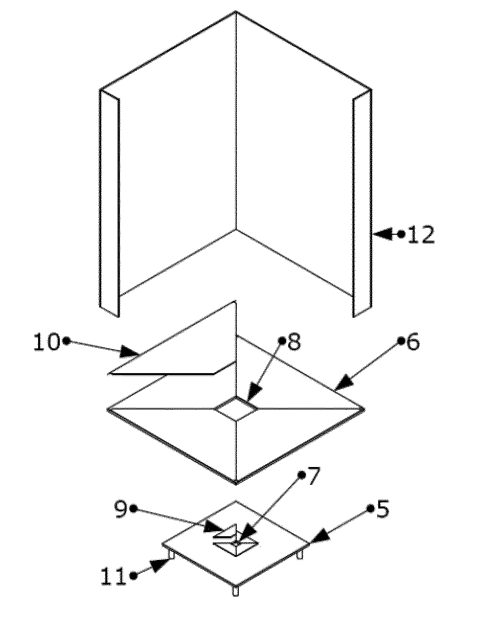
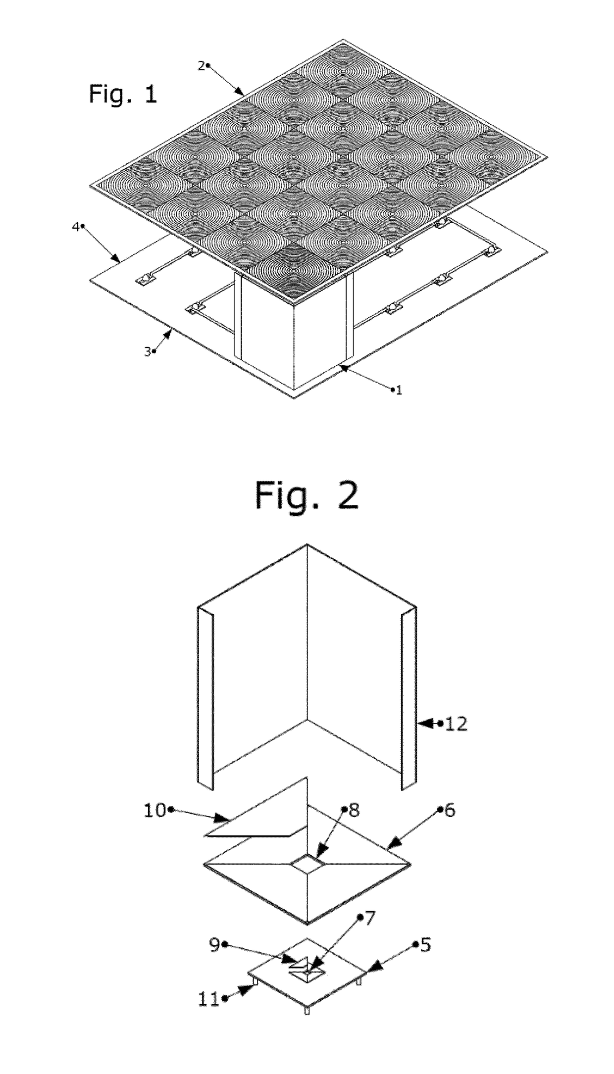
[0038]FIG. 1 is another view of the CPV system, or module, according to one aspect of the present invention. The sensing device 1 is integrated within the CPV device, together forming a single module. The sensing device is located in between a panel composed of a plurality of primary optical elements POE 2 and a receiver panel 3 comprising a plurality of CPV receivers 4. In order to allow the internal components to be shown, the CPV module walls have been omitted. It can be observed that the plane formed by the plurality of POE elements 2 and the receiver panel 3 are parallel to each other. The sensing device is installed on top of one of the CPV recei...


PUM


Abstract

The present invention refers to a sensing device for sensing the alignment with respect to the sun of a concentration photovoltaic CPV device of the type which comprises at least one principal optical element POE and a CPV receiver, a CPV system, or module, comprising a CPV receiver and an integrated sensing device, and an optimized method for aligning a concentration photovoltaic CPV system with respect to the sun.

Description

[0001]This application is a national phase of International Application No. PCT / EP2013 / 057875 filed Apr. 16, 2013 and published in the English language, which claims the benefit of U.S. Provisional Application No. 61 / 624,406 filed Apr. 16, 2012.TECHNICAL FIELD[0002]The present invention relates generally to the field of concentration photovoltaic CPV devices and systems, and more particularly to the fine tuning of solar tracking control systems in CPV systems.BACKGROUND OF THE INVENTION[0003]Concentration photovoltaic CPV technology uses optics such as lenses or curved mirrors to concentrate a large amount of sunlight onto a small area of solar photovoltaic PV cells to generate electricity. They therefore function under high concentration of light (normally more than 100 suns).[0004]Compared to non-concentrated photovoltaic systems, CPV systems can save money on the cost of the solar cells, since a smaller area of photovoltaic material is required. As a smaller PV area is required, ...

Claims


Application Information

Patent Timeline
Patent Type & Authority Patents(United States)
IPC IPC(8): G01B11/26H01L31/054H02S20/32G01S3/786F24S50/20
CPCG01S3/7861F24J2/38H02S20/32H01L31/0543Y02E10/52Y02E10/47F24S50/20
Inventor PARDELL VILELLA, RICARD
Owner RICARD PARDELL VILELLA
Why Eureka
Try Eureka