
Dispensing device and method of dispensing contents from a pouch

a technology of a dispenser and a pouch, which is applied in the field of dispensers, can solve the problems of increasing the cost of packaging, limiting the use of dispensers and pouches, and limited availability of economical or universal dispensers adapted for use with such pouches, and achieves the effect of generating minimal was

Inactive Publication Date: 2018-01-02
KIM DAE SIK
View PDF11 Cites 0 Cited by
  • Summary
  • Abstract
  • Description
  • Claims
  • Application Information

AI Technical Summary

Benefits of technology

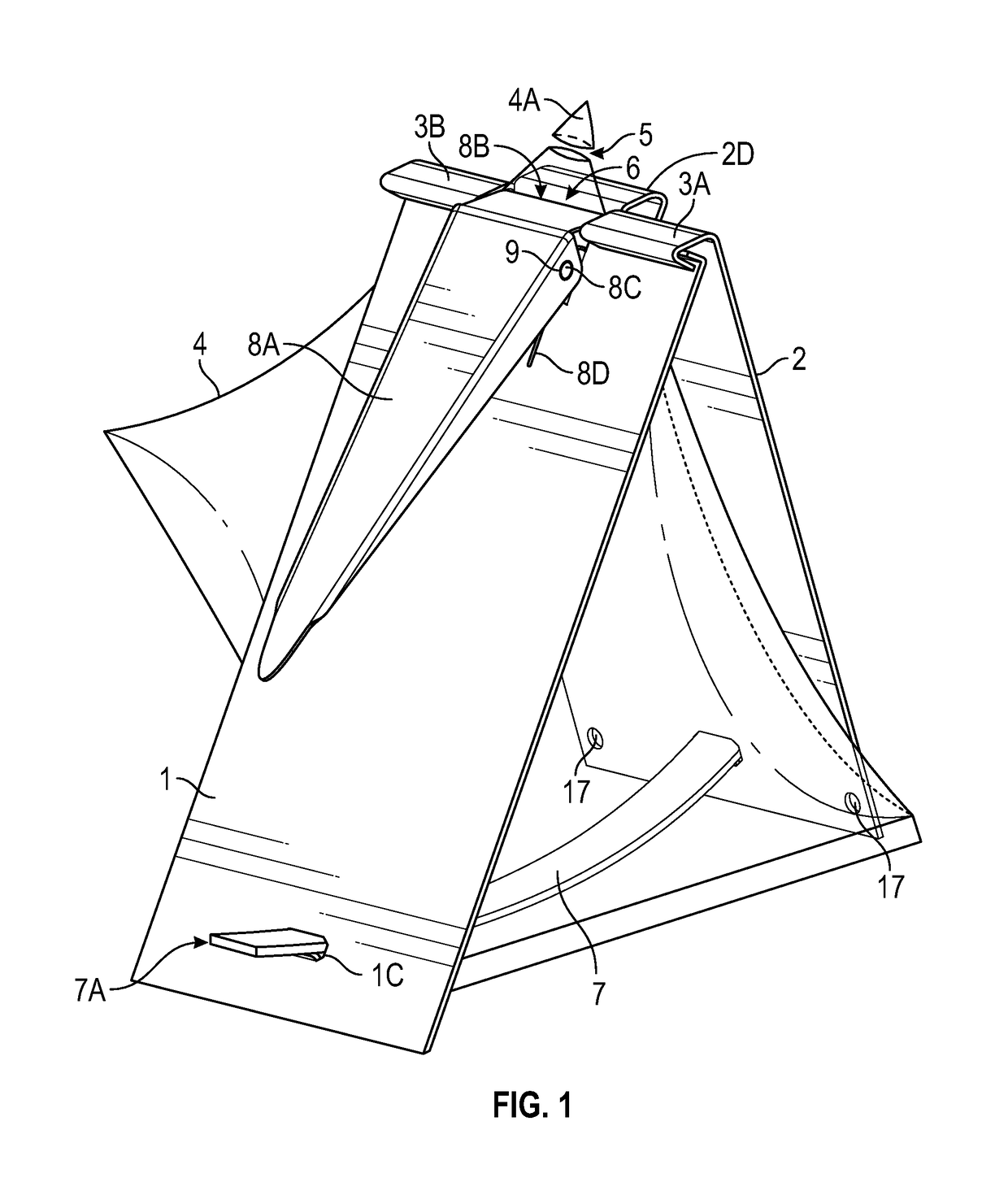
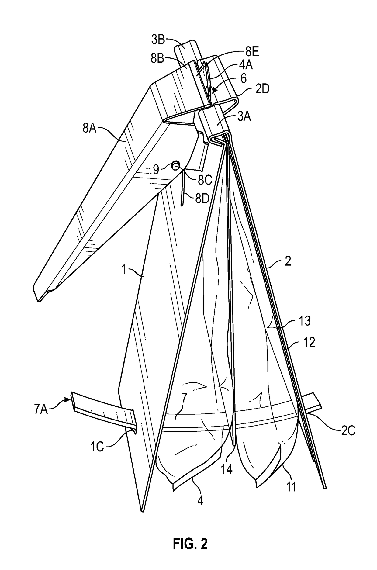
This invention is a dispensing device that allows users to easily dispense, heat, and mix liquid or viscous materials from pouches. The device includes two plates that can be partially hinged, allowing pouches to be positioned between them. A valve assembly is provided to control the dispensing of material from the pouches. The device can be used in industries such as building supply, health care, and personal care products. The invention also provides a combination of the device and pouches, allowing for the dispensing and heating of materials. The method of using the device involves inserting pouches between the plates and controlling the flow rate by selectively heating the pouches. The technical effects of this invention include improved efficiency, flexibility, and the ability to control the dispensing and heating of materials from pouches.

Problems solved by technology

Although flat pack pouches are widely used in the construction industry to pack cement, sand, and pre-mixed concrete, and in the food industry to pack sugar, flour, bulk soup, and condiments, other consumer products such as lotions, sanitizers, and paints are not sold in flat pack pouches because the availability of economical or universal dispensers adapted for use with such pouches is limited.
Such modifications increase the cost of packaging and limit how the dispensers and pouches can be used.

Method used


Image

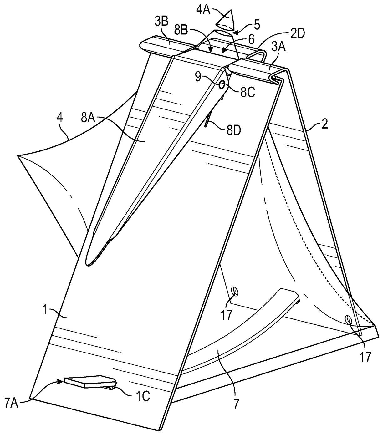
  • Dispensing device and method of dispensing contents from a pouch
  • Dispensing device and method of dispensing contents from a pouch
  • Dispensing device and method of dispensing contents from a pouch

Examples


Embodiment Construction

[0024]Particular terminology is used in the description below for convenience and to help guide the reader. The terminology is not limiting and includes the words actually used and any synonyms, derivatives, and terms of similar import. Likewise, the embodiments of the invention illustrated and described below are provided as examples only and are not intended to restrict the true spirit and scope of this invention as expressed in the claims. Terms that refer to orientation, such as “top” or “bottom,” refer to the orientation of the features of the invention as they appear on the drawing page. When used to refer to a surface of a plate, the term “outer” refers to the surface that will not be in contact with a pouch, heating element, insulating element, or combination thereof. The term “inner” refers to the surface of the plate that is adapted to contact a pouch, heating element, or insulating element.

[0025]In the embodiment of FIG. 1, the top edge of a rectangular plate 1 and top ed...


PUM

PropertyMeasurementUnit
forceaaaaaaaaaa
insulatingaaaaaaaaaa
flexibleaaaaaaaaaa

Abstract

A device for and method of using the device to dispense pourable material from one or more pouches is provided. The device comprises a pair of hinged plates between which one or more pouches can be positioned. The plates of the device are joined by a ratcheting element that secure the plates and any pouches positioned between them. When a squeezing force is applied to the plates, the plates exert pressure upon the one or more pouches to cause the contents of the pouch(es) to be expelled. The ratcheting element is adapted to adjust automatically in response to the force exerted upon the plates. A device adapted to heat and dispense the contents of the one or more pouches is also provided.

Description

CROSS REFERENCE TO RELATED APPLICATIONS[0001]Not ApplicableFEDERALLY SPONSORED RESEARCH OR DEVELOPMENT[0002]Not ApplicableNAMES OF PARTIES TO A JOINT RESEARCH AGREEMENT[0003]Not ApplicableINCORPORATION-BY-REFERENCE OF MATERIAL SUBMITTED ON A COMPACT DISC OR AS A TEXT FILE VIA THE OFFICE ELECTRONIC FILING SYSTEM[0004]Not ApplicablePRIOR DISCLOSURES BY THE INVENTOR[0005]Not ApplicableBACKGROUND OF THE INVENTION[0006]This invention relates generally to a device for and method of dispensing pourable material from one or more pouches, each pouch having one or more acute or right-angled corners that can be removed to form a dispensing spout.[0007]A simple and economical means of packaging pourable discrete solid particles, a liquid, or mixture thereof is to seal such materials between two flexible sheets to form what is known as a pillow or flat pack pouch. This type of pouch is easy to fill, provides a flat surface area for printing, and can be readily packaged in a box or other rigid co...

Claims


Application Information

Patent Timeline
Patent Type & Authority Patents(United States)
IPC IPC(8): B05C17/005B65D47/36
CPCB05C17/00583B05C17/00523B65D47/36A47K5/122B05C17/00553B65D75/5816B65D75/5866B65D83/0055
Inventor KIM, DAE SIK
Owner KIM DAE SIK
Learn More