
Solar module frame

a solar module and frame technology, applied in the field of frames, can solve the problems of limited energy sources on earth, frame weight, inconvenient delivery, installation, repair, etc., and achieve the effects of reducing the overall weight of the frame, improving the power generation efficiency of the solar module, and maintaining a certain level of strength

Active Publication Date: 2017-12-26
NEO SOLAR POWER CORP
View PDF29 Cites 0 Cited by
  • Summary
  • Abstract
  • Description
  • Claims
  • Application Information

AI Technical Summary

Benefits of technology

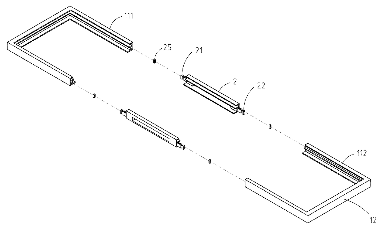
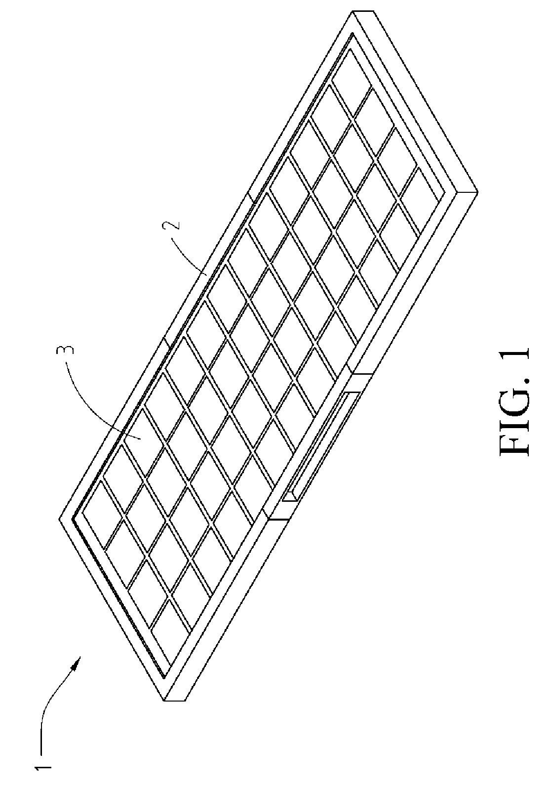
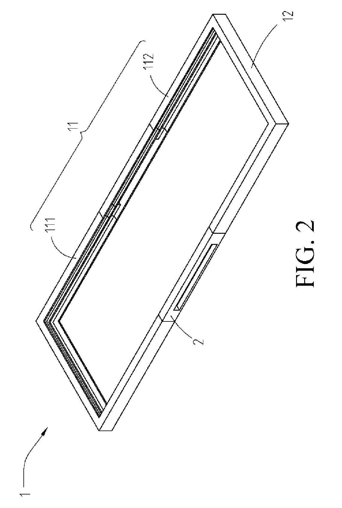
[0007]In view of this, the present invention provides a solar module frame using a composite structure, where at least one border of the solar module frame is formed by two segments and one connection component, and structures and / or materials of the two segments and the connection component are different, so as to reduce an overall weight of the frame and maintain a certain level of strength. An opening may further be provided on the connection component, so that air at the back of the solar module can communicate with ambient air through the opening, thereby solving the heat dissipation problem, and further improving power generation efficiency of the solar module. In addition, only a part of the original frame is changed to be made of a material having workability, that is, borders and a connection component that are made of different materials are used to form the solar module frame; therefore, the solar module frame has the advantage of workability, and maintains mechanical strength of the original frame.
[0009]In conclusion, in the solar module frame according to the present invention, with the workability of a connection component, an opening is provided, so that the problem of heat dissipation at the back of the solar module is solved, and power generation efficiency of the solar module is improved. In addition, in the solar module frame according to the present invention, a connection component having workability is used to replace a part of the original frame; therefore, mechanical strength of the original frame can be maintained. Besides, in the connection component of the solar module frame according to the present invention, a single-wall structure or a double-wall structure in combination with material replacement is used to achieve effects of maintaining the frame strength and saving manufacturing costs.

Problems solved by technology

However, energy sources on the Earth are limited; therefore, people from all over the world are dedicated to development of alternative energy, among which the development of solar power generation conforming to the appeal of environment protection is most popular.
To maintain a high weight bearing capacity and a pressure resisting capability of a solar module, a conventional solar module frame is formed by four integrally formed metal borders, and shapes of the four borders are substantially the same; consequently, the frame is heavy, and thus is inconvenient to deliver, install, and repair.
However, the conventional photoelectric conversion efficiency is low, and most light energy is converted into heat energy; moreover, the solar module is exposed to the sun for a long time, causing the solar module to operate at a very high temperature, and therefore power of the solar module decreases as the temperature increases.
However, the solar module is very close to the ground (or the roof); therefore, heat energy at the bottom of the solar module cannot be effectively dissipated and the bottom is overheating, which further causes problems of a decrease in conversion efficiency of the solar module, a decline in the service life thereof, and even burnout of elements.

Method used


Image

  • Solar module frame
  • Solar module frame
  • Solar module frame

Examples


first embodiment

[0033]First, the connection component 2 of a single-wall structure is described. Referring to FIG. 5A and FIG. 6, FIG. 6 is a schematic three-dimensional view of the connection component according to the present invention. The connection component 2 further includes an external wall 231, a support wall 232, a first clamping wall 233, and a second clamping wall 234. The external wall 231 of the connection component 2 has a first side edge and a second side edge parallel to the first side. The support wall 232 of the connection component 2 is perpendicularly connected to the first side edge of the external wall 231, and the first clamping wall 233 is perpendicularly connected to the second side edge of the external wall 231. The second clamping wall 234 is perpendicularly connected to the external wall 231, is parallel to the first clamping wall 233, and is at a certain distance from the first clamping wall 233, that is, the second clamping wall 234 is disposed between the first clamp...

third embodiment

[0043]In the connection component 2 according to the present invention, the connection component 2 further includes a pad 25, disposed on the first connection end 21 or the second connection end 22. Referring to FIG. 3, in this embodiment, the pad 25 is a ring-shaped object and is sleeved in a groove of the first connection end 21 or the second connection end 22. The groove is provided to prevent the pad 25 from sliding on the first connection end 21 or the second connection end 22. Herein, the pad 25 is made of an elastic material, such as foamed plastic, but the present invention is not limited thereto.

[0044]In addition, in the solar module frame 1 according to an embodiment of the present invention, the first border 11 further includes a first locking hole and a second locking hole. The first locking hole is provided on the first segment 111, and the second locking hole is provided on the second segment 112. Furthermore, the two locking holes may be provided on the external walls...


PUM


Abstract

A solar module frame includes two first borders and two second borders. At least one first border includes a first segment and a second segment, where one end of the first segment is connected to one end of the second border, and one end of the second segment is connected to one end of the other second border. The solar module frame includes at least one connection component. One end of the connection component is connected to the other end of the first segment, and the other end of the connection component is connected to the other end of the second segment. Each of the first segment, the second segment, and the connection component includes an external wall, a support wall, a first clamping wall, and a second clamping wall. Each of the first segment and the second segment includes an internal wall.

Description

CROSS-REFERENCES TO RELATED APPLICATIONS[0001]This non-provisional application claims priority under 35 U.S.C. §119(a) on Patent Application No. 103121474 filed in Taiwan, R.O.C. on 2014 Jun. 20, the entire contents of which are hereby incorporated by reference.BACKGROUND[0002]Technical Field[0003]The present invention relates to a frame applied to a solar module, and particularly, to a lightweight solar module frame having heat dissipation and ventilation functions.[0004]Related Art[0005]With the development of science and technology, demand for energy increases with each passing day. However, energy sources on the Earth are limited; therefore, people from all over the world are dedicated to development of alternative energy, among which the development of solar power generation conforming to the appeal of environment protection is most popular.[0006]To maintain a high weight bearing capacity and a pressure resisting capability of a solar module, a conventional solar module frame i...

Claims


Application Information

Patent Timeline
Patent Type & Authority Patents(United States)
IPC IPC(8): H02S30/10
CPCH02S30/10Y02E10/47F24S25/20Y02E10/50
Inventor WU, MENG-HSIULIN, HUNG-YANGCHEN, CHIEN-LIANGLIN, CHING-HUANGCHUNG, CHANG-KUEIHUNG, SEN-HSIANG
Owner NEO SOLAR POWER CORP
Learn More