Connecting apparatus for creating a connection between a measuring instrument/valve block and a pipeline

a technology for connecting apparatuses and valve blocks, which is applied in the direction of valve housings, instruments, screw threaded joints, etc., can solve the problems of frequent conflicts between manufacturers and users, no longer being able to accept leakage tightness guarantees, and no longer being able to screw second connecting apparatuses into the metering orifice devices by rotation. , to achieve the effect of permanent reliable function and simple and fast installation

Active Publication Date: 2017-12-26
ARMATURENFAB FRANZ SCHNEIDER
View PDF17 Cites 0 Cited by
  • Summary
  • Abstract
  • Description
  • Claims
  • Application Information

AI Technical Summary

Benefits of technology

[0012]Starting from the referenced prior art, the present invention is based on the technical problem or the object of disclosing a connecting apparatus of the type referred to in the introduction which can be economically produced, enables a simple and fast installation, especially in the case of connecting apparatuses with an associated shutoff valve, and ensures a permanently reliable function.
[0015]A constructionally, particularly simple and preferred embodiment is distinguished by the fact that the upper edge region of the first connecting device which faces away from the pipeline has an outwardly pointing connecting flange and an end-face sealing surface, the lower edge region of the second connecting device facing the pipeline has a male thread and an end-face sealing surface, and the connecting unit is designed as a nut unit with a female thread and an inwardly pointing inner flange arranged in the lower edge region facing the pipeline, wherein the outer flange of the first connecting unit fits behind the inner flange of the nut unit and the female thread of the nut unit is screwed onto the male thread of the second connecting device so that by means of the inner flange and the outer flange the end-face sealing surfaces are clamped to each other with sealing effect.
[0016]This embodiment ensures a particularly simple installation. The first connecting device is introduced into the nut unit in this case until the connecting flange comes to butt against the inner flange. After the screwing of the first connecting device into the metering orifice device, and after attaching the second connecting device, this can then be clamped in a simple manner by rotating the nut unit together with the first connecting device without the second connecting device having to execute a rotation. At the same time, the second connecting device can be positioned so that the flange corresponds to the connecting interface of the valve block or of the measuring instrument.
[0021]In order to ensure a stable connection of the connecting apparatus to the metering orifice device or to the pipeline, an advantageous embodiment is distinguished by the fact that the first connecting device has a male thread onto which can be screwed a clamping nut with female thread, wherein the clamping nut can be clamped directly or indirectly on the surface. This variant is advantageous if a flat connecting surface is present. An alternative embodiment, which ensures a high connecting stability even in the case of curved surfaces, is distinguished by the fact that beneath the clamping nut provision is made for a baseplate with through-openings through which the first connecting device can pass, in certain sections, in the longitudinal direction, which baseplate can be clamped on the surface of the pipeline by means of the clamping nut.

Problems solved by technology

In this case, however, the following problems ensue: Since the measuring instrument operates according to the principle of differential pressure measurement there is always a requirement for two connecting apparatuses which are to be arranged at a relative small distance from each other since the metering orifice device, to which are connected the connecting apparatuses, have to be of a relatively compact design in order to deliver reliable values.
As a result, with the first connecting apparatus installed the second connecting apparatus can no longer be screwed into the metering orifice device by rotation since the projecting shutoff valve collides with the first connecting apparatus when being screwed in.
As a result, the following disadvantages ensue: The valve has to be installed at the work site so that a leak test or strength test by the valve manufacturer cannot be carried out and therefore no guarantee for leak tightness can be accepted either.
If now during practical operation leaks occur, conflicts frequently occur between manufacturer and user since the leak can be caused by a faulty valve or a by faulty installation.
In the case of two-part embodiments, in which the two connecting devices are connected by means of a flange, the shutoff valve can admittedly already be installed beforehand but there is the disadvantage that the connecting device, which has to be screwed into the metering orifice device, has to be already installed in position so that the connection to the valve block can be made.

Method used


Image

  • Connecting apparatus for creating a connection between a measuring instrument/valve block and a pipeline
  • Connecting apparatus for creating a connection between a measuring instrument/valve block and a pipeline
  • Connecting apparatus for creating a connection between a measuring instrument/valve block and a pipeline

Examples


Embodiment Construction

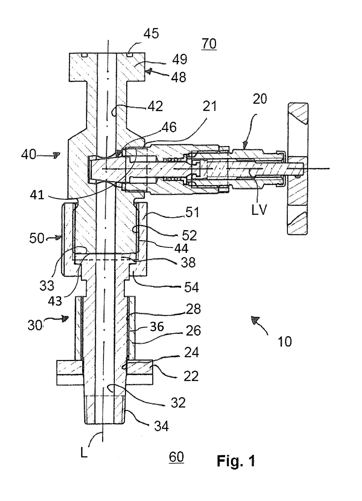
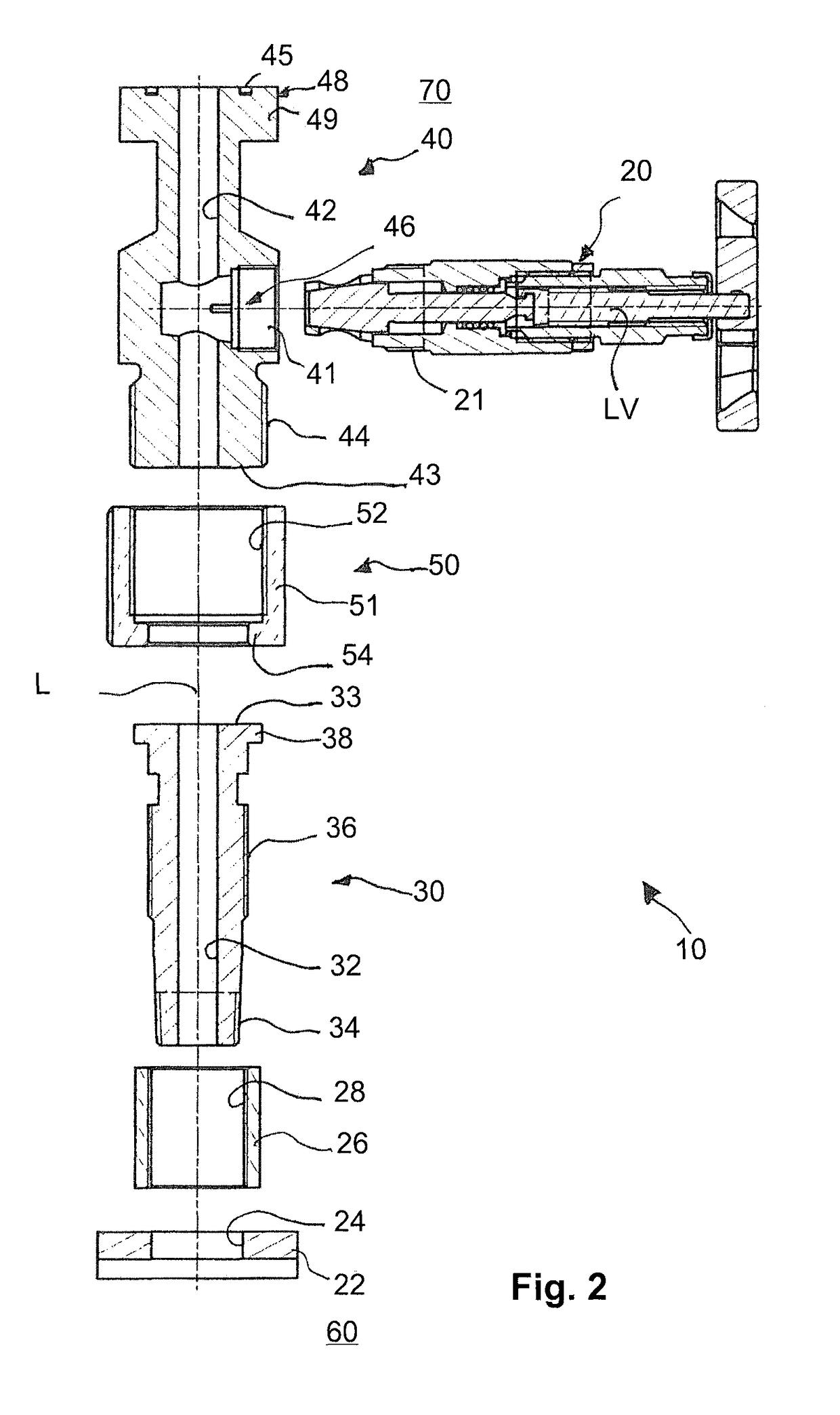
[0032]Shown greatly schematized in FIG. 6 is the field of application of a connecting apparatus 10 according to the invention. In the figures, the lower side is basically provided with the designation 60 and the upper side is basically provided with the designation 70 so that the terms “upper side” and “lower side” used in the further embodiments are clearly defined.

[0033]Provision is made in the lower side for a pipeline 16, which can be a natural gas pipeline, for example, through which flows natural gas in the fluid flow direction F. Installed in the pipeline 16 is a metering orifice device 18 with an orifice unit 19 provided on the inside so that in the region of this metering orifice device 18 there is a cross-sectional constriction for the through-flowing fluid so that different pressure ratios result directly upstream of the orifice unit 19 and directly downstream of the orifice unit 19 and are evaluated for determining the flow rate. The evaluation is carried out via a measu...


PUM


Abstract

A connecting apparatus for creating a connection to a measuring instrument or to a valve block / valve with a measuring instrument, and a connection to a pipeline or to a metering orifice device installed in a pipeline comprises: a first connecting device that provides a sealing connection to the pipeline or to the metering orifice device with a first recess extending through in the longitudinal direction, and a second connecting device that provides a sealing connection to the measuring instrument or to the valve block / valve with a second recess extending through in the longitudinal direction. The first and second connecting devices are interconnected with sealing effect. The connecting unit is designed so that the sealing connection can be created solely by rotation of the connecting unit without rotating the first and second connecting devices.

Description

[0001]This application claims the benefit of German Patent Application No. 102014005783.6, filed Apr. 23, 2014, which is incorporated by reference in its entity herein.FIELD OF THE INVENTION[0002]The present invention relates to a connecting apparatus for creating a connection to a measuring instrument or to a valve block / valve with a measuring instrument, and a connection to a pipeline or to a metering orifice device installed in a pipeline, having a first connecting device for the direct or indirect sealing connection to the pipeline or to the metering orifice device with a first recess extending through in the longitudinal direction, and having a second connecting device for the direct or indirect sealing connection to the measuring instrument or to the valve block / valve with a second recess extending through in the longitudinal direction, wherein the first and second connecting devices are interconnected with sealing effect.BACKGROUND OF THE INVENTION[0003]In pipelines, especial...

Claims


Application Information

Patent Timeline
Patent Type & Authority Patents(United States)
IPC IPC(8): F16L39/00F16L15/00F16L19/025F16L41/00G01F1/00G01F1/40G01F1/42F16L19/02F16K27/02F16K3/24F16L23/00F16L41/10
CPCF16L19/0231F16K3/246F16K27/02F16L15/00F16L19/025G01F1/00G01F1/40G01F1/42F16L41/008F16L41/10F16L23/003
Inventor KELLER, STEFANHAFFNER, MARKUS
Owner ARMATURENFAB FRANZ SCHNEIDER
Why Eureka
Try Eureka