Power negotiation in daisy-chained systems

a power negotiation and daisy chain technology, applied in the direction of instruments, data switching details, liquid/fluent solid measurements, etc., can solve the problems of insufficient communication and processing over load complexity, and achieve the effect of reducing connection requirements

Active Publication Date: 2017-12-19
SIGNIFY HLDG BV
View PDF10 Cites 4 Cited by
  • Summary
  • Abstract
  • Description
  • Claims
  • Application Information

AI Technical Summary

Benefits of technology

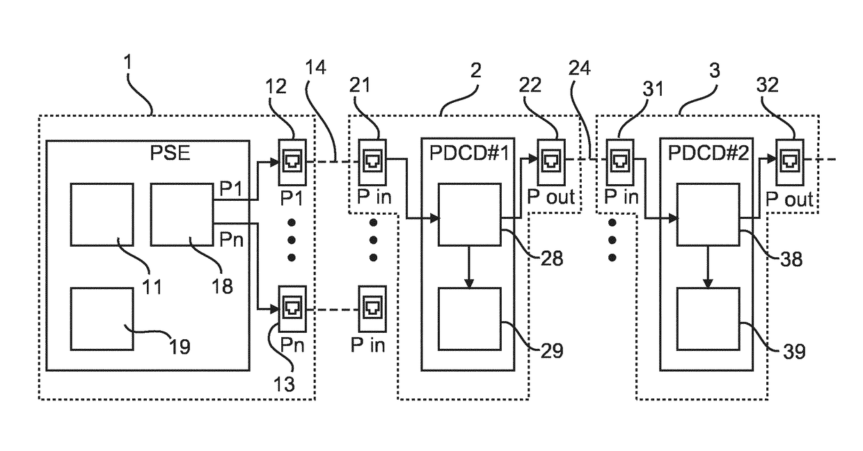
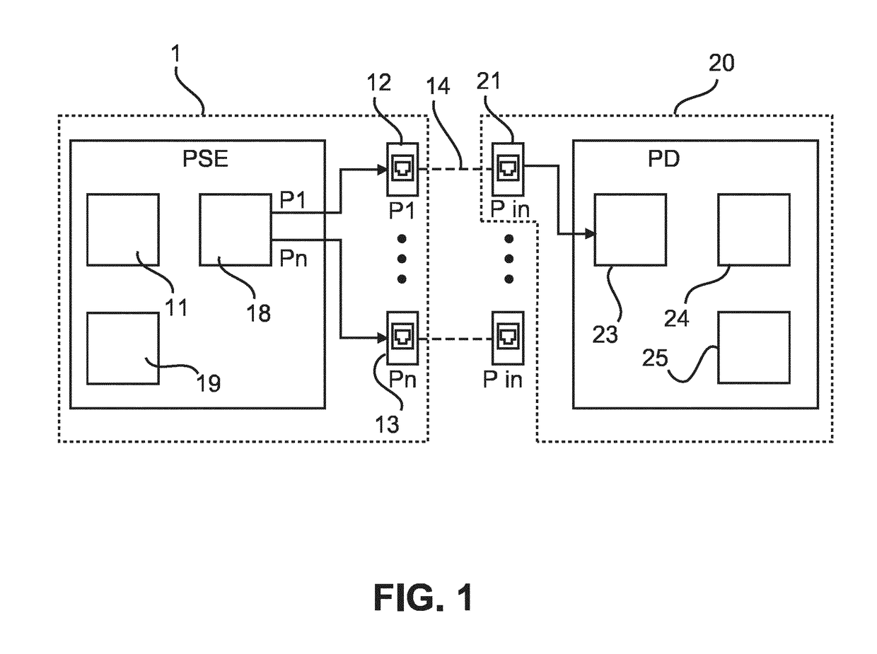
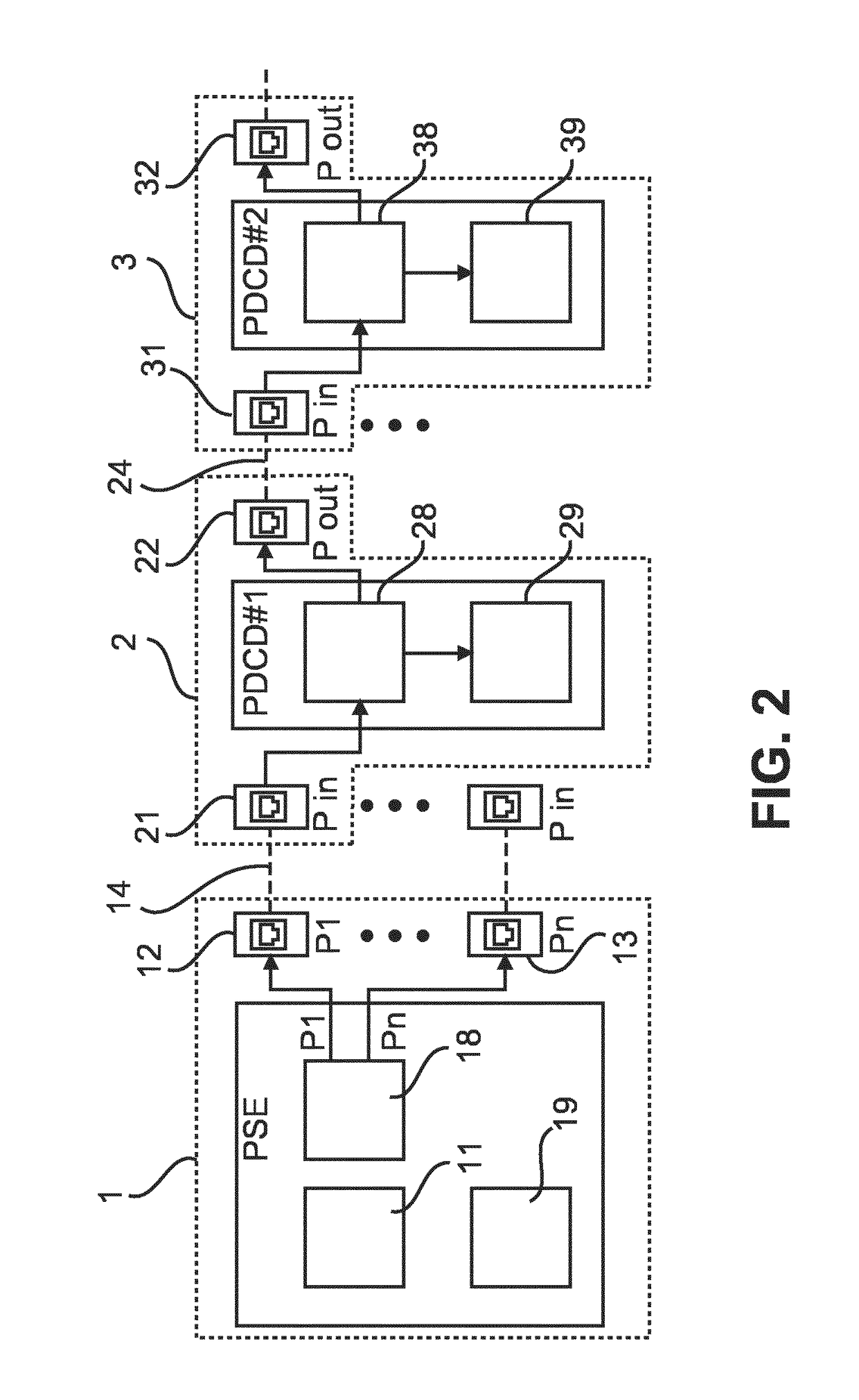
[0014]Accordingly, a device for power negotiation in a PoE network, i.e. a PoE device, can be used in a chain of devices, wherein the PoE device can receive power requests from a subsequent device, which is preferentially also a PoE device, and wherein the PoE device can negotiate power to be received by the PoE device with a preceding PoE device or with a PoE power source to which the input port of the PoE device may be connected. The power received by the PoE device is preferentially only partly used by the PoE device, wherein a part of the received power is forwarded to one or several subsequent devices in the chain of devices. Thus, power negotiations can be done in a daisy chained system while multiple mechanisms can be presented to mitigate the issue of stepwise exploring the power requests along the chain and still keeping the negotiation quick and without many cycles required. The proposed chain configuration or daisy chaining leads to reduced total cable length and average thickness of cable bundle.
[0016]According to a second aspect, the chain controller may be adapted to negotiate via the input port an own power amount of the device plus a predetermined additional power amount, if the chain controller detects that a power source device is connected to the input port and that the subsequent device is connected to the output port. This ensures quick negotiation and fast power-up, since the first load device in the chain configuration does not have to wait for requests from subsequent load devices. According to another option, the chain controller may be adapted to perform power negotiation with the subsequent device via the output port, if the chain controller detects that a power amount negotiated via the input port has been received, and to subsequently re-negotiate power at the input port in response to a negotiation result at the output port. Thereby, a minimum amount of power is always claimed from the power source device.
[0017]According to a third aspect, if the chain controller detects that a power source device is connected to the input port, the chain controller may be adapted to negotiate via the input port a predetermined maximum power amount deliverable by a power source device, the device is adapted to subsequently only supply power to the chain controller in a first phase, the chain controller may be adapted to wait for a power request from the subsequent device at the output port in a second phase, the power request indicating a requested power sum of all subsequent devices of the chain configuration, and the chain controller may be adapted to instruct via the output port that all subsequent devices can activate to their full requested power if the requested power sum is less or equal the negotiated maximum power amount. This provides the advantage that all load devices of the chain configuration negotiate simultaneously and are powered at the same time. As another option, if the chain controller detects that the device is a second device in the chain configuration, the chain controller may be adapted to trigger via the input port negotiation of a lower power amount corresponding to the requested power sum. This ensures that only the minimum power amount is negotiated for the chain configuration.
[0019]Furthermore, if the chain controller detects that the device is not the last device of the chain connection and that no power source device is connected to the input port, the chain controller may be adapted to determine an own sequence number of the device based on a sequence number included in the power request received via the output port, to generate an enhanced power request by adding information about the own sequence number and an own power amount to the received power request, and to forward the enhanced power request via the input port. Thereby, load devices within the chain configuration are allowed to determine and add their sequence number to the power request so that the first load device which is connected to the power source device knows the total amount or sum of requested power and the origin of the individual power requests.
[0020]According to a fourth aspect, the device may comprise a memory for storing a power request value, wherein the chain controller may be adapted to determine a power request value received with the power request at the output port, to add the stored power request value to the received power request value in order to obtain a sum value, and to transmit the sum value via the input port if the chain controller detects that another device of the chain configuration is connected to the input port. As a further option, the chain controller may be adapted to perform power negotiation at the input port using the sum value if the chain controller detects that a power source device is connected to the input port. Additionally, the chain controller may be adapted to perform power negotiation at the input port using the sum value if the chain controller detects that a power source device is connected to the input port. Thereby, long time delays can be prevented, since the first load device does not have to wait until the last load device is requesting power.
[0021]According to a fifth aspect which can be combined with at least one of the first to fourth aspects, the chain controller may be adapted to store at least one of a result of power negotiation and addresses of neighboring devices in the chain configuration so as to be re-called after a power-off state. Thereby, fast system recovery or power-up can be ensured.

Problems solved by technology

As PoE supply systems for power distribution inside of buildings get into the view of the industry, specific drawbacks of these networks need to find solutions in order to get these direct current powered networks (so called “DC-Grids”) widely employed.
However, in the new application field of lighting systems or similar load systems with often small loads with low local computing and communication requirements, sometimes the overhead of communication and processing compared to the load complexity is inappropriate.

Method used


Image

  • Power negotiation in daisy-chained systems
  • Power negotiation in daisy-chained systems
  • Power negotiation in daisy-chained systems

Examples


first embodiment

[0038]The above first embodiment provides the advantage that a simple power budget negotiation can be provided at all chain stages. Moreover, no hardware or software or protocol modifications are required at the PSE. The last-in-chain device can be a legacy PoE load. Hardware implementation of the PDCDs can be kept simple, esp. power supply logic, since they do not need to differentiate between full operation (load+chain controller) and stand-by operation (chain controller only).

[0039]The first embodiment can be enhanced in that each PDCD, starting with the first PDCD next to the PoE, initially only negotiates on its input port only the amount of power corresponding to its own power consumption plus a predefined power amount for one further device. This additional amount of power consumption may only be requested if it is detected by the chain controller that a further device is connected at the output port, e.g. by a physical connection. The additional amount may correspond e.g. to...

second embodiment

[0042]FIG. 4 shows a schematic block diagram which indicates steps of a power negotiation procedure according to a

[0043]Similar to the first embodiment, the first load device L1 (e.g. a spot lamp) claims in a first message or request S1 maximum amount of available power and gives down-stream what remains reduces this issue. However, in the second embodiment, the device L1 does not switch on the load but powers only the processor (of the chain controller) in a first negotiation phase (initialization phase). So, even if for instance 20 load devices form a chain and their processing driving takes 100 mW each, only 2 W will be consumed in the first phase in total and all processors get power. In the second phase the load devices of the chain or chain members signal upstream (i.e. towards the PSE) how much power they would like claiming.

[0044]Thus, during the initialization phase only the first load device L1 in the chain starts the negotiation (for the full power for the entire chain). ...

third embodiment

[0061]In the following, a third embodiment is described, where power negotiation is configured to prevent for long time delays when the first load device (e.g. lamp or luminaire) has to wait until the last load device is requesting power. This can also be used before the load devices are installed because it houses in the load device itself and the load devices can be provided with small amount of power, probably a battery or energy scavenger, to send the amount of power to be used by the load device.

[0062]According to the third embodiment, a power request value (indicating the amount of required power) is embedded or stored in the load device itself. Once the load device is attached to one or more neighbor devices (e.g. detected by discovering a physical connection on the upstream port), it gives this request number and the neighbor devices add this to their own request number. This is done until the connector to the PSE delivering the power is reached and then it is checked whethe...


PUM


Abstract

The invention relates a method and apparatus for distributing power in DC-grid systems, wherein power negotiations are done in a daisy chained system. Multiple mechanisms are presented mitigating the issue of stepwise exploring the power requests along a chain and still keeping the negotiation quick and without many cycles required.

Description

CROSS-REFERENCE TO PRIOR APPLICATIONS[0001]This application is the U.S. National Phase application under 35 U.S.C. §371 of International Application No. PCT / EP2014 / 065513, filed on Jul. 18, 2014, which claims the benefit of European Patent Application No. 13177271.7, filed on Jul. 19, 2013. These applications are hereby incorporated by reference herein.FIELD OF THE INVENTION[0002]The invention relates to the field of methods and devices for distributing power in DC grid systems, such as—but not limited to—lighting systems.BACKGROUND OF THE INVENTION[0003]US 2012 / 0286574 A1 discloses an electric power system with a first unit equipped with a first power source, a first rechargeable battery connected to an output of the first power source and a first power consuming portion connected to an output of the first rechargeable battery. The electric power system further comprises a second rechargeable battery and an electrical power line for sharing electric power between the first recharge...

Claims


Application Information

Patent Timeline
Patent Type & Authority Patents(United States)
IPC IPC(8): H04L12/10G06F1/26
CPCG06F1/26H04L12/10G06F1/266
Inventor WENDT, MATTHIASYSEBOODT, LENNARTERDMANN, BOZENAALARCON-RIVERO, MANUEL EDUARDODRAAIJER, MAURICE HERMAN JOHAN
Owner SIGNIFY HLDG BV
Why Eureka
Try Eureka