Multi-fuel engine system

a fuel-based engine and engine technology, applied in the direction of machines/engines, electric control, combustion-air/fuel-air treatment, etc., can solve the problems of reducing durability, limiting the opportunity of operating engines with natural gas, and reducing the application cost of existing engine architectures, so as to reduce the cost of fuel and minimize engine modifications

Active Publication Date: 2017-12-19
GE GLOBAL SOURCING LLC
View PDF28 Cites 2 Cited by
  • Summary
  • Abstract
  • Description
  • Claims
  • Application Information

AI Technical Summary

Benefits of technology

[0006]In this way, an intake manifold configured to introduce gaseous fuel (e.g., natural gas) to at least one cylinder may include an insert located between the intake manifold and the cylinder head of the cylinder to promote mixing of the gaseous fuel and intake air. Vehicles that are currently configured to operate with only diesel fuel (for example) may be retrofitted with the intake manifold and insert to operate with both diesel fuel and natural gas, while minimizing engine modifications to achieve the benefit of lower cost fuel.

Problems solved by technology

However, many existing engines are typically configured with only a single, liquid (e.g., diesel) fuel supply, limiting the opportunities for operating engines with natural gas.
However, such an approach may be costly and difficult to apply to existing engine architectures, even on a small scale.
Without significant redesign, the modifications required to the cylinder head may compromise the integrity of the head casting and likely result in reduced durability.

Method used


Image

  • Multi-fuel engine system
  • Multi-fuel engine system
  • Multi-fuel engine system

Examples


Embodiment Construction

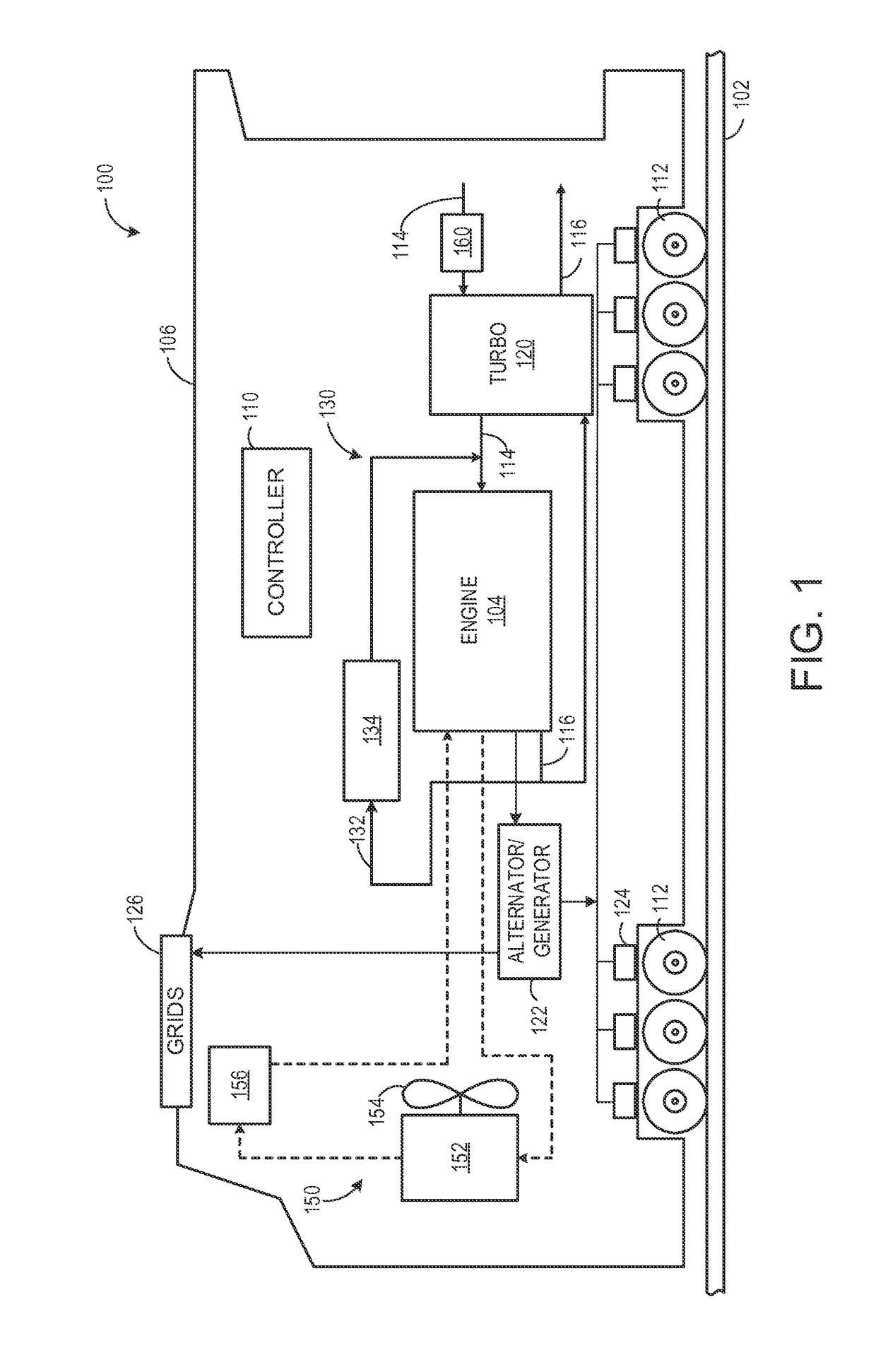
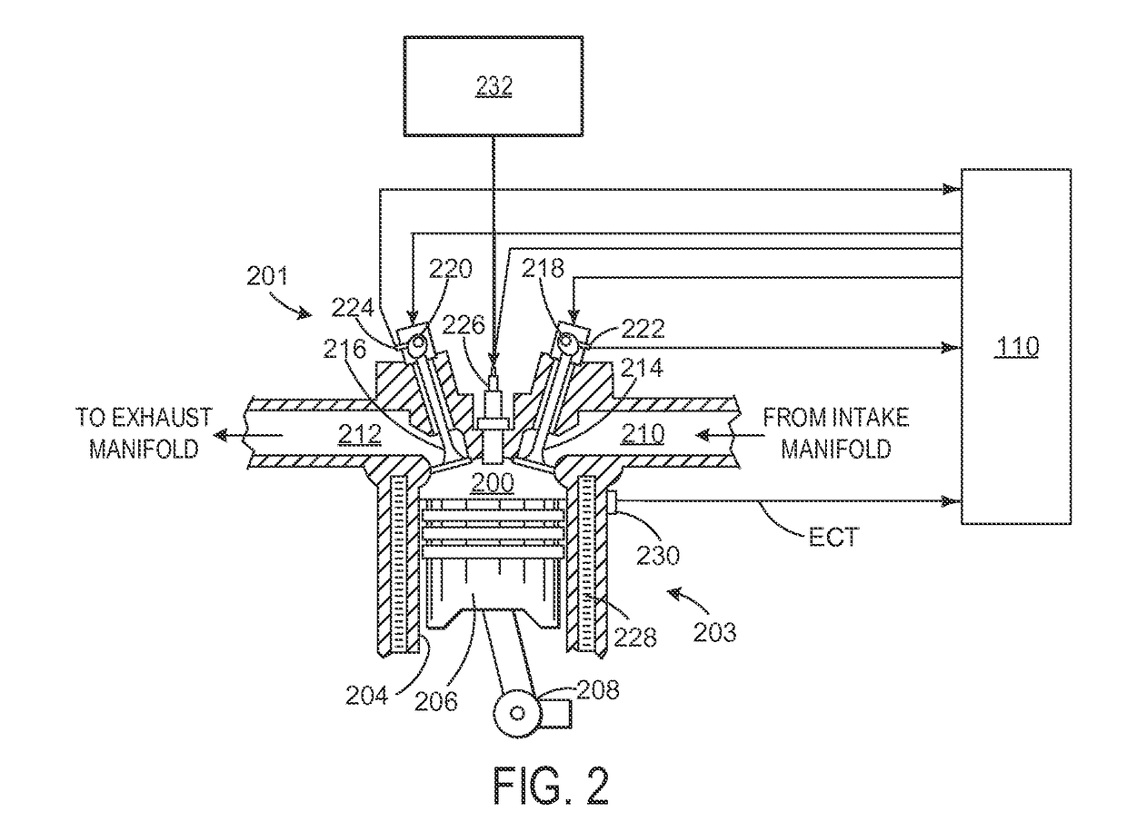
[0016]The following description relates to various embodiments of an intake manifold to supply intake air and gaseous fuel to a plurality of cylinders of a multi-cylinder engine. In other embodiments, the intake manifold further comprises a coolant outlet to direct coolant from the engine to a coolant system component, such as a heat exchanger or other component. One or more cylinders of the plurality of cylinders may be supplied with the gaseous fuel via respective gas admission valves mounted on the intake manifold. By supplying the gaseous fuel via the intake manifold, a single gas supply passage and internal gas routing to power assemblies may be provided, reducing the potential number of gas-sealing joints and thus the potential for leakage of gaseous fuel out of the engine. The intake manifold also provides gas admission geometry flexibility for air-gas mixing optimization. Additionally, mounting the gas admission valves on the intake manifold, as opposed to other locations (s...


PUM

PropertyMeasurementUnit
pressureaaaaaaaaaa
inner circumferenceaaaaaaaaaa
combustionaaaaaaaaaa

Abstract

Various methods and systems are provided for an intake manifold for an engine. In one example, an insert comprises an annular body having a top surface, bottom surface, inner surface, and outer surface. The insert further comprises a first groove for coupling an intake air port of an intake manifold to a cylinder head, a second groove for circulating gaseous fuel received from a gas runner of the intake manifold, and one or more openings to fluidically couple the second groove to an interior of the intake air port. The insert is configured to mix gaseous fuel and intake air at a coupling location between the intake manifold and the cylinder head.

Description

RELATED APPLICATIONS[0001]This application claims priority to U.S. Provisional Application No. 61 / 929,642, filed Jan. 21, 2014, the entire contents of which are hereby incorporated by reference for all purposes.FIELD[0002]Embodiments of the subject matter disclosed herein relate to an engine, engine components, and an engine system, for example.BACKGROUND[0003]Vehicles, such as locomotives, may include a prime mover that is powered by a fuel source to generate mechanical energy. In one example, mechanical energy generated by the prime mover may be converted to electrical energy that is used to power traction motors and other components and systems of the vehicle. In some examples, the prime mover may be a combustion engine that is fueled by diesel, gasoline, or other liquid petroleum distillates. In other examples the engine may additionally or alternatively utilize a gaseous fuel, such as natural gas.[0004]In light of its favorable energy content, natural gas may be used as a fuel ...

Claims


Application Information

Patent Timeline
Patent Type & Authority Patents(United States)
IPC IPC(8): F01P9/00F02M35/116F02D19/10F02D41/00F02M21/02F02M21/04F02M35/16F02M35/10F02B75/22F01P3/20F01P7/14F02M26/05F01P11/06F02F1/24F01P11/04F02B75/18
CPCF02M35/10288F02D41/0027F02M21/023F02M21/029F02M21/0278F02M21/0281F02M21/04F02M21/042F02M35/10262F02M35/116F02M35/164F02D19/105Y02T10/32F01P3/20F01P11/04F01P11/06F01P2007/146F01P2060/08F01P2060/10F02B75/22F02B2075/1848F02B2201/064F02F1/24F02M26/05F02M35/10268F02M35/10144F02M35/10321F02M35/10347Y02T10/12Y02T10/30F02M35/112F05C2225/08
Inventor GRUSCHOW, ALEXISTRASK, LESLIE ORINDILLEN, ERIC RICHARDROTH, JOHN STEPHENFELION, MATTHEW JOSEPH
Owner GE GLOBAL SOURCING LLC
Why Eureka
Try Eureka