
Aroma diffuser using an aroma capsule

a diffuser and aroma technology, applied in the direction of gaseous substances, disinfection, lighting and heating apparatus, etc., can solve the problems of increasing the cost, user's smell of aroma wax residues, and the likely leakage of essential oil from the container, so as to facilitate and efficiently replace the aroma capsule

Active Publication Date: 2017-12-19
HSIAO MING JEN
View PDF24 Cites 9 Cited by
  • Summary
  • Abstract
  • Description
  • Claims
  • Application Information

AI Technical Summary

Benefits of technology

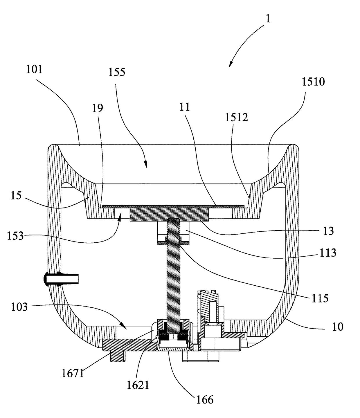
[0007]In view of the problems of the prior art, the present invention provides an aroma diffuser using an aroma capsule. The aroma diffuser can be simply and smoothly combined with a disposable aroma capsule. Since the aroma capsule is disposable, a new aroma capsule can replace the used aroma capsule easily.
[0008]Thus, the present invention provides an aroma diffuser using an aroma capsule, which reduces the assembly cost and errors.
[0010]When using the aroma diffuser using an aroma capsule, the user can place an aroma capsule in the holding chamber of the holder member through the free end of the heat conduction device, and use a power supply unit to provide electricity to the heating element for generating heat to heat the heat conduction device so that the generated heat energy can be transferred through the heat conduction device to the aroma capsule, causing the aroma capsule to release a fragrant vapor toward the outside of the aroma diffuser.
[0011]Unlike the prior art design in which the hollow housing and the holder member are made from different materials and separately mounted, the invention has the hollow housing and the holder member integrally made in one piece without any labor-consuming assembly steps, and thus, the invention saves the component cost of the holder member and enhances the structural stability. During the operation of the heating element to heat the aroma capsule, the heat energy in the holder member and the hollow housing is prohibited from being transferred to the printed circuit board and other electronic components, avoiding thermal damage to the electronic components.
[0013]The aroma diffuser further comprises an aroma capsule placed in the holding chamber of the holder member. The aroma capsule has a bottom side thereof supported on the lower upright wall and kept in contact with the heat conduction device, and an opposing top side thereof suspended in the upper arched wall and defining with the upper arched wall an arched gap therebetween. After the contained aroma in the aroma capsule is used up, the user can insert his or her plump fingers through the arched gap to pick up the used aroma capsule from the holding chamber of the holder member for replacement, and then place a new aroma capsule in the holding chamber inside the holder member of the aroma diffuser quickly. When compared to the prior art design in which the holder member and an attached external member, the holder member and the hollow housing in accordance with the present invention are integrally made in one piece, and thus, the invention greatly the assembly cost and errors. The design of the invention allows the user to replace the aroma capsule conveniently and efficiently.

Problems solved by technology

The essential oil is likely to be leaked from the container as the container is toppled over.
During the cleaning process, the user is likely to be stained by the aroma wax residues.
An external assembly step is necessary to install the holder member, increasing the cost.
Further, the holder member is not orthopedically designed for finger installation.
It is not convenient for the user to place the aroma capsule in the narrow inside space of the heat conduction container in the aroma diffuser with the fingers, or to take the used aroma capsule out of the aroma diffuser.
This disadvantage affects the convenience and efficiency of the use of the aroma capsule in the aroma diffuser.

Method used


Image

  • Aroma diffuser using an aroma capsule
  • Aroma diffuser using an aroma capsule
  • Aroma diffuser using an aroma capsule

Examples


Embodiment Construction

[0021]The following illustrative embodiments are provided to illustrate the disclosure of the present invention, these and other advantages and effects can be apparently understood by those in the art after reading the disclosure of this specification. The present invention can also be performed or applied by other different embodiments. The details of the specification may be on the basis of different points and applications, and numerous modifications and variations can be devised without departing from the spirit of the present invention.

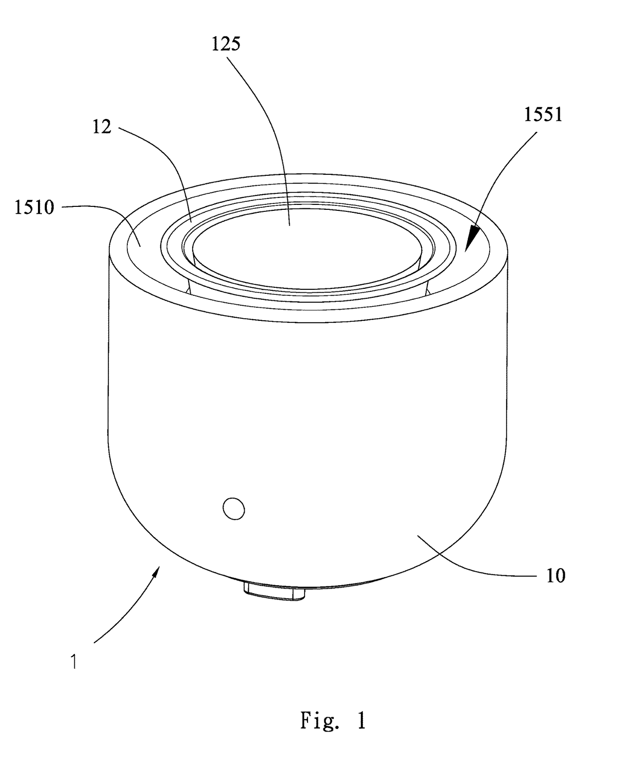
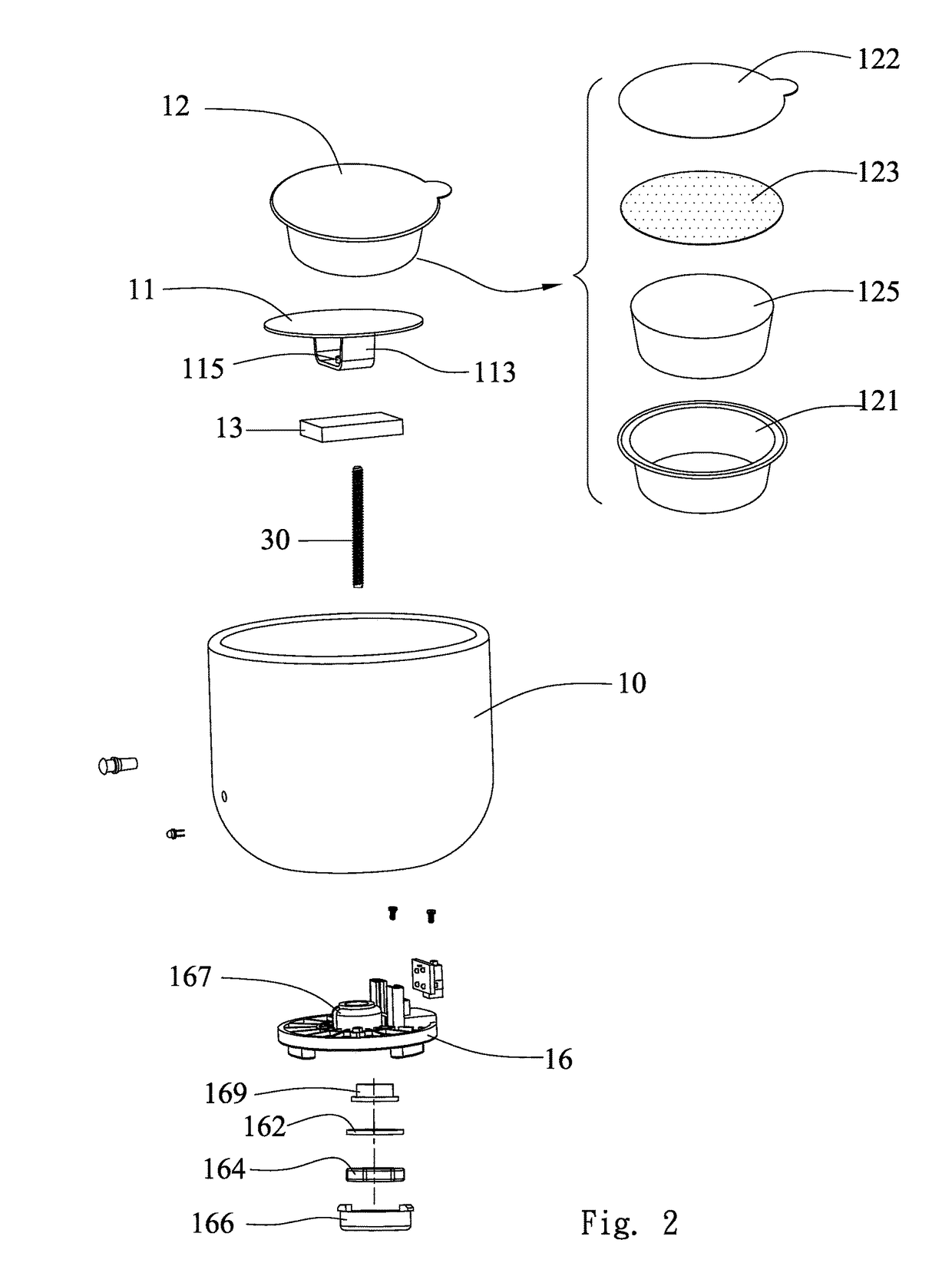
[0022]Refer to FIGS. 1-4. In an embodiment according to the present invention, an aroma diffuser 1 having an aroma capsule comprises a hollow housing 10, a heat conduction device 11, and a heating element 13. The hollow housing 1 comprises a first opening 101, a second opening 103 and a holder member 15. The first opening 101 is defined in a top side of the hollow housing 10. The second opening 103 is defined in an opposing bottom side of the hol...


PUM

PropertyMeasurementUnit
structural stabilityaaaaaaaaaa
heat energyaaaaaaaaaa
electrical insulationaaaaaaaaaa

Abstract

An aroma diffuser using an aroma capsule is disclosed to include a hollow housing including a first opening on a top side thereof, a second opening on a bottom side thereof and an integrated holder member downwardly inwardly extended from a top side thereof and defining therein a holding chamber facing toward the first opening, a heat conduction device mounted in the holding chamber, and a heating element mounted at a bottom side of the heat conduction device and kept in contact with the heat conduction device. Thus, an aroma capsule can be placed in the holding chamber and heated by the heating element to release fragrant vapor. After the aroma contained in the aroma capsule is used up, the aroma capsule can be replaced conveniently and rapidly.

Description

CROSS-REFERENCES TO RELATED APPLICATION[0001]The present invention is a continuation-in-part of patent application Ser. No. 14 / 042,162 filed on Sep. 30, 2013 and Ser. No. 14 / 157,302 filed on Jan. 16, 2014.BACKGROUND OF THE INVENTION[0002]1. Field of the Invention[0003]This invention relates to an aroma diffuser technology and more particularly, to an aroma diffuser using an aroma capsule.[0004]2. Description of Related Art[0005]U.S. Pat. Nos. 8,066,420, 8,262,277 and 8,147,116 disclose an aroma diffuser, which includes a power supply, a heating source, essential oil or aroma wax, and a container for the aroma wax to be contained therein. The essential oil is likely to be leaked from the container as the container is toppled over. After the aroma wax contained in the container is evaporated completely and before a new aroma wax is placed in the container, the user needs to take aroma wax residues out from the container and then to clean the container. During the cleaning process, the...

Claims


Application Information

Patent Timeline
Patent Type & Authority Patents(United States)
IPC IPC(8): F22B29/06B01D3/06A61L9/03
CPCA61L9/03A61L2209/133A61L2209/135
Inventor HSIAO, MING JEN
Owner HSIAO MING JEN
Learn More