
Dual-beam sector antenna and array

a dual-beam sector, array technology, applied in the field of radio communication, can solve the problems of affecting the coverage of the desired cellular sector, the use of 6 of these antennas on a tower, and the cost of the array, so as to improve the coverage of the desired cellular sector, the effect of improving the azimuth sidelobe suppression and less interferen

Active Publication Date: 2017-11-28
COMMSCOPE TECH LLC
View PDF56 Cites 18 Cited by
  • Summary
  • Abstract
  • Description
  • Claims
  • Application Information

AI Technical Summary

Benefits of technology

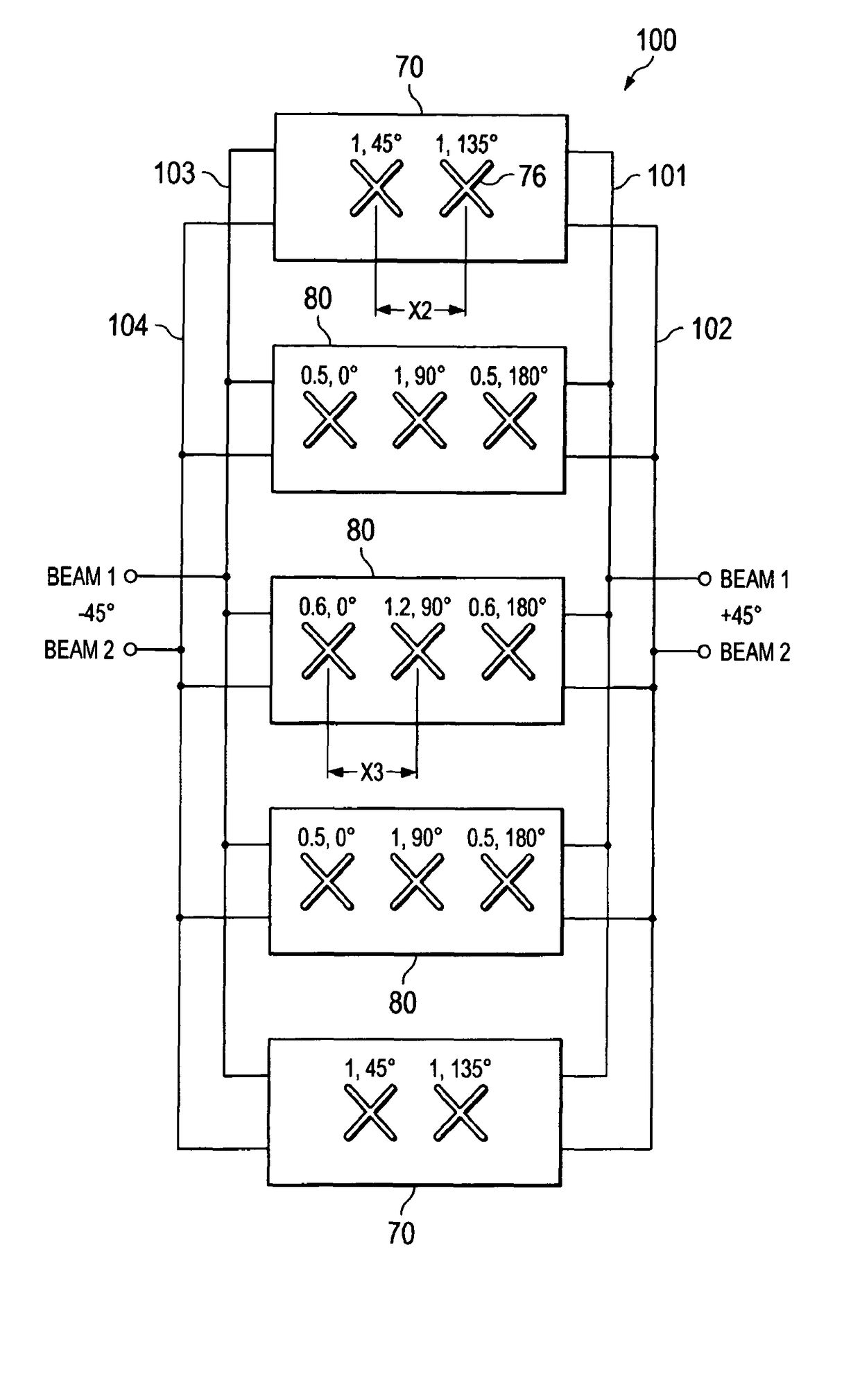
The present invention is a dual-beam antenna that integrates different types of modules to form a complete array, which helps improve the antenna's performance. The key to the modules is an improved beam forming network (BFN) that allows for optimized amplitude and phase distribution for both beams. By using 2×2, 2×3, and 2×4 BFNs in a complete array, the invention provides improved performance in terms of azimuth sidelove suppression, coverage of a desired cellular sector, and less interference. The antenna's beams are optimized and adjustable, with low sidelobes and backlobes. Overall, the invention results in improved cell efficiency and a better user experience.

Problems solved by technology

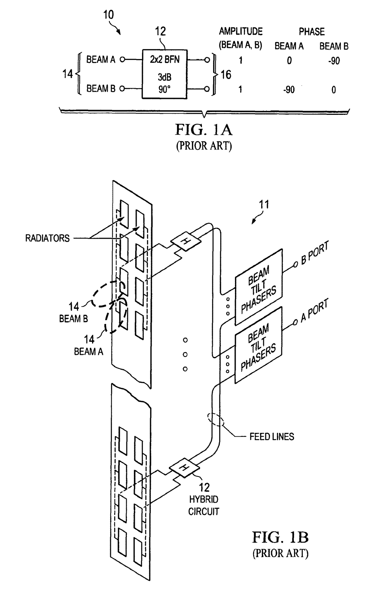
However, the use of 6 of these antennas on a tower, where each antenna is typically two times wider than the common 65° AzBW antenna used in 3-sector systems, is not compact, and is more expensive.
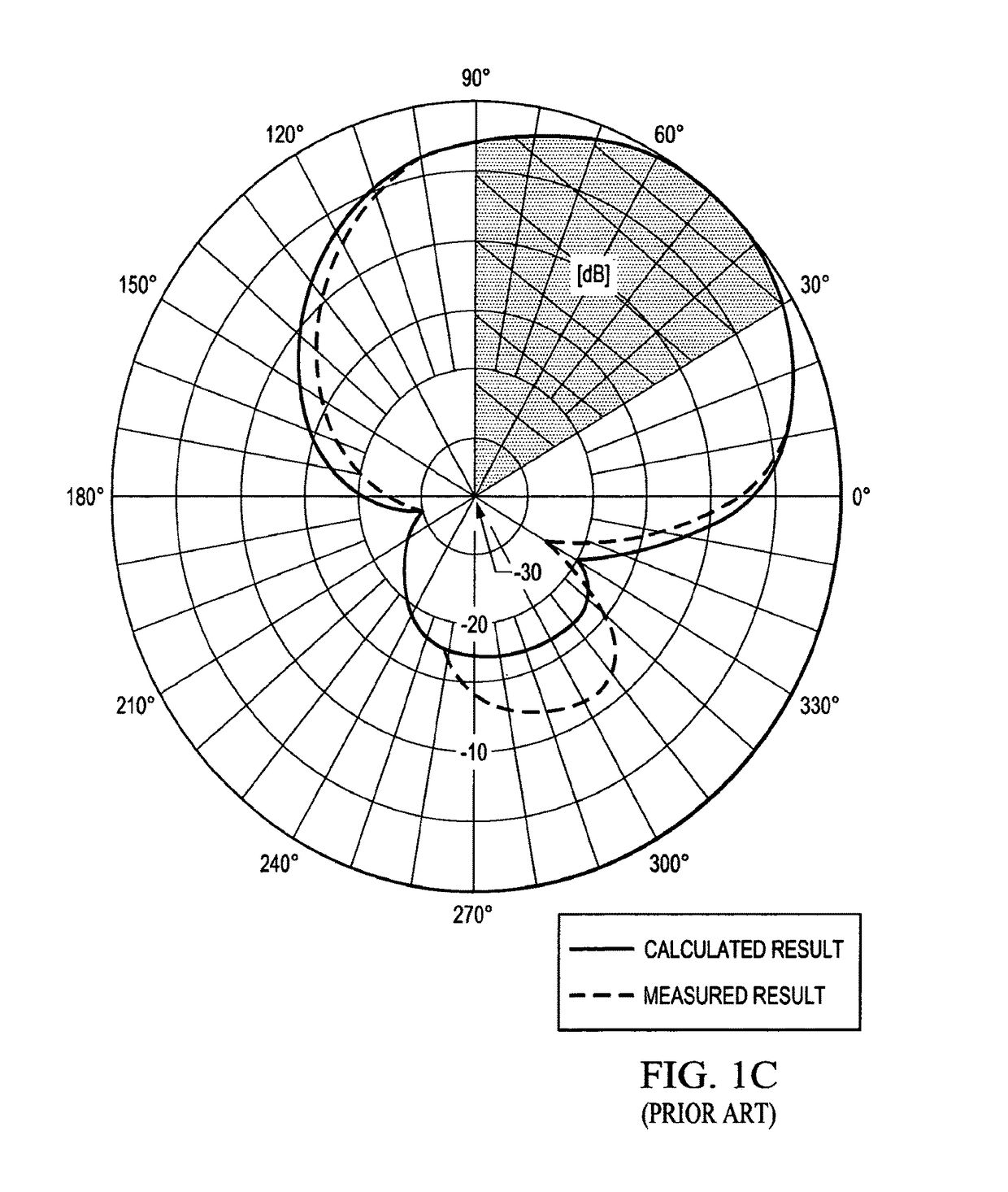
The main drawback of this prior art antenna as shown in FIG. 1C is that more than 50% of the radiated power is wasted and directed outside of the desired 60° sector for a 6-sector application, and the azimuth beams are too wide (150°@−10 dB level), creating interference with other sectors, as shown in FIG. 1D.
Moreover, the low gain, and the large backlobe (about −11 dB), is not acceptable for modern systems due to high interference generated by one antenna into the unintended cells.
Another drawback is vertical polarization is used and no polarization diversity.

Method used


Image

  • Dual-beam sector antenna and array
  • Dual-beam sector antenna and array
  • Dual-beam sector antenna and array

Examples


Embodiment Construction

[0027]Referring now to FIG. 2A, there is shown one preferred embodiment comprising a bidirectional 2×3 BFN at 20 configured to form 2 beams with 3 columns of radiators, where the two beams are formed at signal ports 24. A 90° hybrid coupler 22 is provided, and may or may not be a 3 dB coupler. Advantageously, by variation of the splitting coefficient of the 90° hybrid coupler 22, different amplitude distributions of the beams can be obtained for radiator coupling ports 26: from uniform (1-1-1) to heavy tapered (0.4-1-0.4). With equal splitting (3 dB coupler) 0.7-1-0.7 amplitudes are provided. So, the 2×3 BFN 20 offers a degree of design flexibility, allowing the creation of different beam shapes and sidelobe levels. The 90° hybrid coupler 22 may be a branch line coupler, Lange coupler, or coupled line coupler. The wide band solution for a 180° equal splitter 28 can be a Wilkinson divider with a 180° Shiffman phase shifter. However, other dividers can be used if desired, such as a ra...


PUM


Abstract

A low sidelobe beam forming method and dual-beam antenna schematic are disclosed, which may preferably be used for 3-sector and 6-sector cellular communication system. Complete antenna combines 2-, 3- or -4 columns dual-beam sub-arrays (modules) with improved beam-forming network (BFN). The modules may be used as part of an array, or as an independent 2-beam antenna. By integrating different types of modules to form a complete array, the present invention provides an improved dual-beam antenna with improved azimuth sidelobe suppression in a wide frequency band of operation, with improved coverage of a desired cellular sector and with less interference being created with other cells. Advantageously, a better cell efficiency is realized with up to 95% of the radiated power being directed in a desired cellular sector.

Description

CROSS REFERENCE TO RELATED APPLICATIONS[0001]This application is a 35 U.S.C. §371 national stage application of PCT International Application No. PCT / US2009 / 006061, filed Nov. 12, 2009, which itself claims priority of Provisional Application U.S. Ser. No. 61 / 199,840 filed on Nov. 19, 2008 entitled Dual-Beam Antenna Array, the teaching of which are incorporated herein. The disclosure and content of both of which are incorporated herein by reference in their entireties. The above-referenced PCT International Application was published in the English language as International Publication No. WO2010 / 059786 A1 on May 27, 2010.FIELD OF THE INVENTION[0002]The present invention is generally related to radio communications, and more particularly to multi-beam antennas utilized in cellular communication systems.BACKGROUND OF THE INVENTION[0003]Cellular communication systems derive their name from the fact that areas of communication coverage are mapped into cells. Each such cell is provided wi...

Claims


Application Information

Patent Timeline
Patent Type & Authority Patents(United States)
IPC IPC(8): H01Q3/00H01Q3/26H01Q3/30H01Q25/00H01Q1/24H01Q21/24H01Q25/02H01Q3/28H01Q3/40H01Q21/06
CPCH01Q3/26H01Q1/246H01Q3/30H01Q25/002H01Q25/02H01Q3/40H01Q21/061H01Q21/24H01Q25/00H01Q3/28
Inventor TIMOFEEV, IGORZIMMERMAN, MARTINCAO, HUYHUA, YANPING
Owner COMMSCOPE TECH LLC
Learn More