Machining tool and cutting head for the machining tool

a technology of machining tool and cutting head, which is applied in the direction of manufacturing tools, shaping cutters, wood boring tools, etc., can solve the problems of increasing the force acting in the screwed coupling, introducing forces, etc., and achieves less of a tendency to tighten, and much more rapid clamping

Active Publication Date: 2017-11-28
KENNAMETAL INC
View PDF23 Cites 1 Cited by
  • Summary
  • Abstract
  • Description
  • Claims
  • Application Information

AI Technical Summary

Benefits of technology

[0008]By contrast with the prior art described at the beginning, the external thread of the cutting head interacting with the internal thread of the holder exclusively has the function of bracing the flat contact area of the cutting head against the counter area on the holder. The cylindrical thread improves the force transmission here between the cutting head and the holder. The centering accuracy of the clamping cone and of the hollow-conical cone contact area expanded by the clamping cone is very high. Moreover, the possibility of the hollow-conical cone contact area expanding in the holder at the same time reduces the wear of the internal thread and the external thread.
[0009]A further advantage is the complete elimination of clamping aids. Because of this elimination of clamping aids and the favorable force transmission via the external and internal threads, the coupling region of the cutting head requires only a very small installation space in the holder, and is consequently specifically suitable for cutting heads with very small shanks. In a preferred configuration, the cutting-edge region is adjoined in the axial direction by a flat collar. The peripheral region of its end face facing away from the cutting-edge region is configured here as a flat contact area. Seen in the axial direction, projecting from the center of the end face of the flat collar there is firstly the cylindrical thread carrier with the external thread and then the clamping cone.
[0010]The axial length of the external thread in a preferred configuration is a maximum of 50% of the length of the cone. This means that the axial length of the thread is less than or equal to half the axial length of the clamping cone. This configuration for its part contributes in turn to the spatial economy of the tool in the coupling region.
[0013]One effect of the comparatively great length of the clamping cone, in particular in combination with the small cone angle, is that easy insertion of the coupling region into the holder and exact centering in the holder are made possible.
[0017]The use of a coarse thread has the advantage that the cutting head can be clamped much more quickly in the holder, and over-tight bracing caused by machining forces of the cutting head in the holder is avoided. The use of a fine thread makes it possible that the screwed coupling can be set very much more smoothly and consequently more precisely.

Problems solved by technology

A disadvantage of this tool is the introduction of forces.
On account of the conical form of the thread, the latter tends to keep tightening itself during the milling machining and thereby increase the forces acting in the screwed coupling.

Method used


Image

  • Machining tool and cutting head for the machining tool
  • Machining tool and cutting head for the machining tool
  • Machining tool and cutting head for the machining tool

Examples


Embodiment Construction

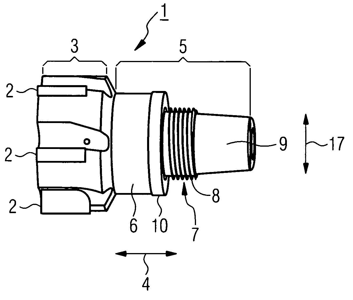
[0022]The cutting head 1 consists of a cutting-edge region 3, bearing a number of cutting edges 2, and of a coupling region 5, adjoining the cutting-edge region 3 in the axial direction 4.

[0023]The coupling region 5 is for its part made up of the flat collar 6, the cylindrical thread carrier 7 and the clamping cone 9. The flat collar 6 in this case adjoins the cutting-edge region 3 in the axial direction 4. Projecting in the axial direction 4 from the end face of the flat collar 6 that is facing away from the cutting-edge region 3 in the axial direction 4 there is the cylindrical thread carrier 7. Formed into the outer lateral surface of the thread carrier 7 is the external thread 8. The thread carrier 7 is in turn adjoined in the axial direction 4 by the clamping cone 9. The outer periphery of the end face of the flat collar 6 that is facing away from the cutting-edge region 3 forms the flat contact area 10. The flat contact area 10 consequently runs in the manner of a ring around ...


PUM

PropertyMeasurementUnit
cone angleaaaaaaaaaa
areaaaaaaaaaaa
axial lengthaaaaaaaaaa

Abstract

A machining tool includes a holder and a cutting head which can be screwed into the holder. The cutting head includes a cutting-edge region and a coupling region. The coupling region includes a flat contact area facing the holder, a cylindrical thread carrier with an external thread adjoining the flat contact area, and a clamping cone adjoining the thread carrier. The holder includes a planar counter-contact area disposed adjacent the flat contact area of the coupling region, a cylindrical internal thread adjoining the planar counter-contact area, and a hollow-conical cone contact area next to the internal thread.

Description

BACKGROUND OF THE INVENTION[0001]The invention relates to a machining tool with a holder and with a cutting head which can be screwed into the holder and relates to such a cutting head. The cutting head for its part comprises a cutting-edge region and a coupling region. Such a cutting head that can be screwed into a holder is known, for example, from U.S. 2001 / 0041089 A1.[0002]On account of the present-day precision production methods for cutting tools, in particular cutting heads, it is possible to produce a cutting head without laborious finishing operations, in particular grinding work on the cutting-edge region, being required at the end of the production process. For reasons of cost, it is desired on the one hand to dispense with clamping aids, for example clamping pins, in the coupling region, and on the other hand to complete the cutting tool without having to carry out remachining in the coupling region of the cutting head to make it fit into the holder.[0003]The periodical ...

Claims


Application Information

Patent Timeline
Patent Type & Authority Patents(United States)
IPC IPC(8): B23C5/10B23B31/11
CPCB23C5/10B23B31/1107B23B31/1122B23C2210/02Y10T408/907Y10T407/19Y10T407/1906Y10T407/1908Y10T407/1946B23C2210/03
Inventor SCHUFFENHAUER, MICHAELXYLANDER, RENE
Owner KENNAMETAL INC
Why Eureka
Try Eureka