
Electrophotographic photosensitive member, process cartridge and electrophotographic apparatus

a photosensitive member and electrophotography technology, applied in the direction of electrographic process apparatus, instruments, optics, etc., can solve the problems of degrading cleaning performance and still allowing improvement, and achieve the effect of reducing a streak-like image d

Active Publication Date: 2017-11-14
CANON KK
View PDF11 Cites 9 Cited by
  • Summary
  • Abstract
  • Description
  • Claims
  • Application Information

AI Technical Summary

Benefits of technology

[0010]The present invention is directed to providing an electrophotographic photosensitive member capable of reducing a streak-like image defect caused in output in a low printing mode performed under a high-temperature and high-humidity environment, and a process cartridge and an electrophotographic apparatus including the electrophotographic photosensitive member.
[0017]According to the present invention, an electrophotographic photosensitive member capable of reducing a streak-like image defect caused in output in a low printing mode performed under a high-temperature and high-humidity environment, and a process cartridge and an electrophotographic apparatus including the electrophotographic photosensitive member can be provided.

Problems solved by technology

On the other hand, an example of a problem occurring because of the increased wear resistance of a surface of the electrophotographic photosensitive member includes degradation of cleaning performance.
Even when the techniques disclosed in Japanese Patent Application Laid-Open No. 2010-26240 and Japanese Patent Application Laid-Open No. 2010-250355 are employed, however, although the cleaning performance can be improved, there still remains room for improvement because a streak-like image defect (hereinafter also referred to as the “H / H initial streak (high temperature / high humidity environmental initial streak)”) is caused on a halftone image having a density of about 30% output after printing in a low printing mode is performed under a high-temperature and high-humidity environment.

Method used


Image

  • Electrophotographic photosensitive member, process cartridge and electrophotographic apparatus
  • Electrophotographic photosensitive member, process cartridge and electrophotographic apparatus
  • Electrophotographic photosensitive member, process cartridge and electrophotographic apparatus

Examples


example 1

[0140]The photosensitive member (1) was loaded in a cyan station of a modified machine of an electrophotographic apparatus (a copying machine) (Trade Name: iR-ADV C5255) manufactured by Canon Inc. used as an evaluation machine, so as to be tested and evaluated as follows.

[0141]The initial potential of the electrophotographic photosensitive member was adjusted by setting conditions of a charging device and an image exposing device so that a dark-area potential (Vd) and a light-area potential (Vl) of the electrophotographic photosensitive member could be respectively −500 V and −180 V under an environment of 30° C. and 80% RH.

[0142]Next, a cleaning blade made of polyurethane rubber having a hardness of 77° was brought into contact with the surface of the electrophotographic photosensitive member at a contact angle of 28° and a contact pressure of 30 g / cm. With a heater (a drum heater) for the electrophotographic photosensitive member placed in an ON state, 200 sheets of a lateral A4 s...

examples 2 to 20

[0143]The electrophotographic photosensitive members shown in Table 3 were respectively evaluated using actual machines in the same manner as in Example 1. The results are shown in Table 3.

[0144]

TABLE 3Electrophotographic PhotosensitiveEvaluation ResultMemberStreakExample 1Photosensitive Member -1CExample 2Photosensitive Member -2CExample 3Photosensitive Member -3BExample 4Photosensitive Member -4BExample 5Photosensitive Member -5AExample 6Photosensitive Member -6AExample 7Photosensitive Member -7AExample 8Photosensitive Member -8AExample 9Photosensitive Member -9AExample 10Photosensitive Member -10BExample 11Photosensitive Member -11AExample 12Photosensitive Member -12AExample 13Photosensitive Member -13AExample 14Photosensitive Member -14AExample 15Photosensitive Member -15AExample 16Photosensitive Member -16AExample 17Photosensitive Member -17AExample 18Photosensitive Member -18AExample 19Photosensitive Member -19AExample 20Photosensitive Member -20A

[0145](Production Examples of ...


PUM


Abstract

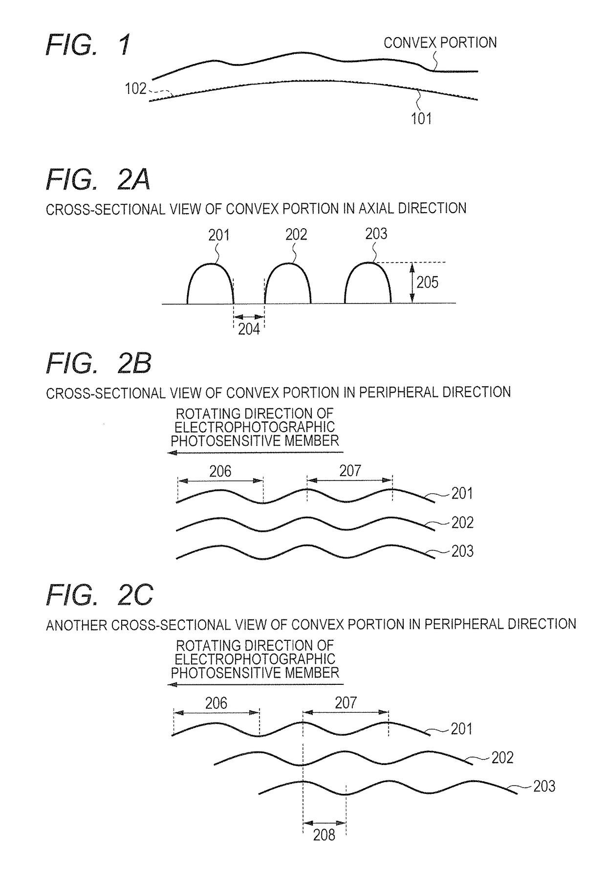
An electrophotographic photosensitive member, a process cartridge and an electrophotographic apparatus wherein a streak-like image defect otherwise occurring in output in a low printing mode performed under a H / H environment can be reduced are provided. A surface of the photosensitive member has a convex and concave portions continuously in a peripheral direction of the photosensitive member, and alternately in an axial direction of the photosensitive member, a width w of the concave portion is 30 to 100 μm, a depth d of the concave portion is 1 to 5 μm, the convex portion has a rising slope and a descending slope in the peripheral direction of the photosensitive member, and a distance from a starting point of the rising slope to an end point of the descending slope and a distance from a starting point of the descending slope to an end point of the rising slope are 300 μm or less.

Description

BACKGROUND OF THE INVENTION[0001]Field of the Invention[0002]The present invention relates to an electrophotographic photosensitive member, a process cartridge and an electrophotographic apparatus.[0003]Description of the Related Art[0004]Since an electrical external force and a mechanical external force for charging and cleaning are applied to a surface of an electrophotographic photosensitive member, the electrophotographic photosensitive member is required to have durability (such as wear resistance) against such external force.[0005]In order to meet such a requirement, an improvement technique of using, in a surface layer of an electrophotographic photosensitive member, a resin having high wear resistance (such as a curable resin) has been conventionally employed.[0006]On the other hand, an example of a problem occurring because of the increased wear resistance of a surface of the electrophotographic photosensitive member includes degradation of cleaning performance.[0007]As a t...

Claims


Application Information

Patent Timeline
Patent Type & Authority Patents(United States)
IPC IPC(8): G03G15/00G03G5/043G03G21/18
CPCG03G21/18G03G5/043G03G5/147G03G15/75
Inventor KITAMURA, WATARUIKARI, KENICHI
Owner CANON KK
Learn More