Stirred tank reactor

a technology of stirring tank and reactor, which is applied in the direction of mixing, rotary stirring mixer, transportation and packaging, etc., can solve the problems of complex construction of this known gas stirring mechanism, substantially high pressure for gas feed, and unsuitable devices, etc., to achieve improved gas utilization degree, simple structure, and high gas-liquid mass transfer coefficient

Active Publication Date: 2017-11-14
METSO OUTOTEC (FINLAND) OY
View PDF18 Cites 2 Cited by
  • Summary
  • Abstract
  • Description
  • Claims
  • Application Information

AI Technical Summary

Benefits of technology

[0014]An advantage of the invention is that the mechanical gas sparging apparatus provides sparging of the gas in very fine bubbles with a simple structure. Further with the provision of the mechanical gas sparging apparatus the stirred tank reactor is able to provide a high gas-liquid mass transfer coefficient and an improved gas utilization degree. A further advantage of the invention is that the gas feed does not become easily blocked. The gas feed does not need a high pressure because it only needs to be greater than the hydrostatic pressure.
[0015]In an embodiment of the invention the mixing power per unit volume inside the dispersion chamber is greater than 0.25 kW / m3.
[0016]In an embodiment of the invention the mixing power per unit volume inside the dispersion chamber is in the range 0.5-2 kW / m3 while the mixing power elsewhere in the reactor tank outside the dispersion chamber is less than 0.5 kW / m3.
[0017]In an embodiment of the invention the second volume of the dispersion chamber is less than 10% of the first volume of the reactor tank.
[0018]In an embodiment of the invention the main impeller has a first diameter and the dispersion chamber has a second diameter which is smaller than the first diameter.
[0019]In an embodiment of the invention the dispersion chamber comprises a wall defining a hollow inner space inside the wall, an upper end which is upwardly open and a lower end which is downwardly open.

Problems solved by technology

At hydrometallurgical applications this kind of devices are not very suitable, since they tend to block up easily.
Further, the problem is that a substantially high pressure for the gas feed is needed because of a great pressure loss caused by the small holes or porous material.
The problem is that the construction of this known gas sparging mechanism is complex and requires installation of at least two mixer mechanisms and electric motors for one stirred tank reactor.

Method used


Image

  • Stirred tank reactor
  • Stirred tank reactor
  • Stirred tank reactor

Examples


example

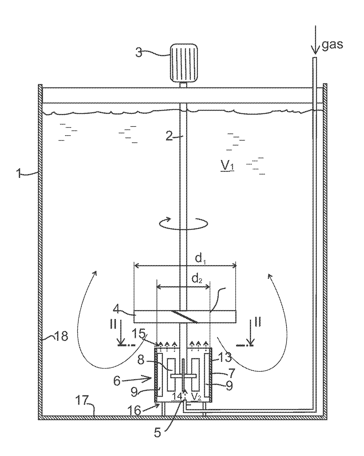
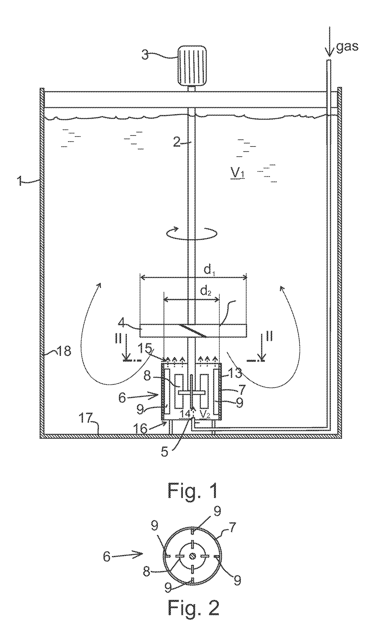
[0067]With reference to FIGS. 14 and 15, laboratory tests were made to show the advantageous effects of the invention. As an example of the invention sodium sulphite solution was oxidized in a cylindrical tank that had flat bottom and inner diameter of 780 mm. Tank was equipped with a rotating agitator, baffles and a gas feed was arranged below the impeller. Solution volume was 485 l, oxygen feed approximately 400 l / h and temperature was kept between 20-25° C. by cooling. Content of dissolved oxygen was monitored with a sensor that was submerged 20 cm below the solution surface. Rotation speed of the agitator was controlled with a frequency converter and power intake of the electric motor was monitored. Gas dispersion efficiency of different configurations was determined by measuring volumetric mass transfer coefficient (kLa-value) and oxygen efficiency with different rotation speeds. Measurement of kLa was based on steady state method in which oxidation of sodium sulphite to sodium...


PUM

PropertyMeasurementUnit
angleaaaaaaaaaa
inner diameteraaaaaaaaaa
temperatureaaaaaaaaaa

Abstract

The invention relates to a stirred tank reactor for gas-liquid mass transfer in a slurry. The reactor includes a reactor tank (1) having a first volume (V1), a drive shaft (2) that extends vertically in the reactor tank, a motor (3) for rotating the drive shaft (2), a main impeller (4) which is a downward pumping axial flow impeller attached to the drive shaft (2) to create a main flow pattern in the reactor tank, and a gas inlet (5) arranged to supply gas into the reactor tank (1) to be dispersed to the liquid. The reactor includes a mechanical gas sparging apparatus (6) comprising a dispersion chamber (7) having a second volume (V2) which is substantially smaller than the first volume (V1) of the reactor tank (1), the dispersion chamber being arranged coaxial with the drive shaft (2), and the gas inlet (5) being arranged to feed gas into the dispersion chamber (7), and mixing means (8, 9, 10, 11, 12) arranged within the dispersion chamber (7) for mixing the gas into liquid by dispersing the gas to fine bubbles before the bubbles enter the main flow pattern. The mixing power per unit volume inside the dispersion chamber (7) is significantly larger than the mixing power elsewhere in the reactor.

Description

CROSS-REFERENCE TO RELATED APPLICATIONS[0001]This is a national stage application filed under 35 USC 371 based on International Application No. PCT / FI2014 / 050068 filed Jan. 29, 2014 and claims priority under 35 USC 119 of Finnish Patent Application No. 20135090 filed Jan. 30, 2013.STATEMENT REGARDING FEDERALLY SPONSORED RESEARCH OR DEVELOPMENT[0002]Not Applicable.THE NAMES OF THE PARTIES TO A JOINT RESEARCH AGREEMENT[0003]Not Applicable.INCORPORATION-BY-REFERENCE OF MATERIAL SUBMITTED ON A COMPACT DISC OR AS A TEXT FILE VIA THE OFFICE ELECTRONIC FILING SYSTEM (EFS-WEB)[0004]Not Applicable.STATEMENT REGARDING PRIOR DISCLOSURES BY THE INVENTOR OR A JOINT INVENTOR[0005]Not Applicable.FIELD OF THE INVENTION[0006]The present invention relates to a stirred tank reactor for gas-liquid mass transfer.BACKGROUND OF THE INVENTION[0007]In hydrometallurgical applications gas is usually fed to a stirred tank reactor below the agitator through a plain pipe. Gas is then dispersed to fine bubbles wi...

Claims


Application Information

Patent Timeline
Patent Type & Authority Patents(United States)
IPC IPC(8): B01F3/04B01F7/22B01F7/06B01F7/00B01F15/00B01F7/18B01F27/71B01F27/91B01F33/40
CPCB01F3/04531B01F3/04517B01F3/04588B01F3/04609B01F7/00641B01F7/06B01F7/22B01F15/00538B01F7/186B01F2215/0463B01F2003/0468B01F2003/04645B01F2003/04673B01F23/232311B01F23/2332B01F23/23341B01F23/23353B01F23/23362B01F23/23363B01F27/192B01F27/9021B01F27/91Y02P10/20B01F23/231B01F23/2323B01F23/233B01F27/71B01F27/86B01F33/402B01F27/90B01F35/3204
Inventor LATVA-KOKKO, MARKORITASALO, TEEMUVAARNO, JUSSI
Owner METSO OUTOTEC (FINLAND) OY
Why Eureka
Try Eureka