Applicator device for a product in stick form and use of same

a technology of application device and product, which is applied in the field of application device for a product, can solve the problems of significant angular rotation between the tubular base and the sleeve, and achieve the effect of reducing the path of angular actuation

Active Publication Date: 2017-11-14
PARFUMS CHRISTIAN DIOR
View PDF7 Cites 5 Cited by
  • Summary
  • Abstract
  • Description
  • Claims
  • Application Information

AI Technical Summary

Benefits of technology

[0017]With these arrangements, the sliding of the stick of product toward the second end is delayed when the end cover means begins to open, then this sliding is accelerated once the end cover means is sufficiently open, which allows the applicator device to travel to the usage position over a reduced path of angular actuation.

Problems solved by technology

They have the disadvantage of requiring significant angular rotation between the tubular base and the sleeve, because the end cover means must be at least partially open before the stick of product can begin to protrude from the casing.

Method used


Image

  • Applicator device for a product in stick form and use of same
  • Applicator device for a product in stick form and use of same
  • Applicator device for a product in stick form and use of same

Examples


first embodiment

A. First Embodiment of the Invention

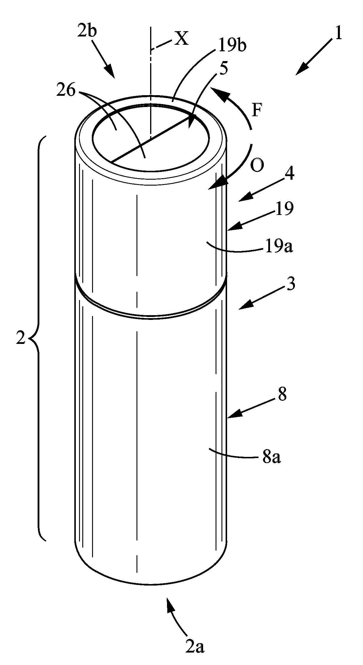
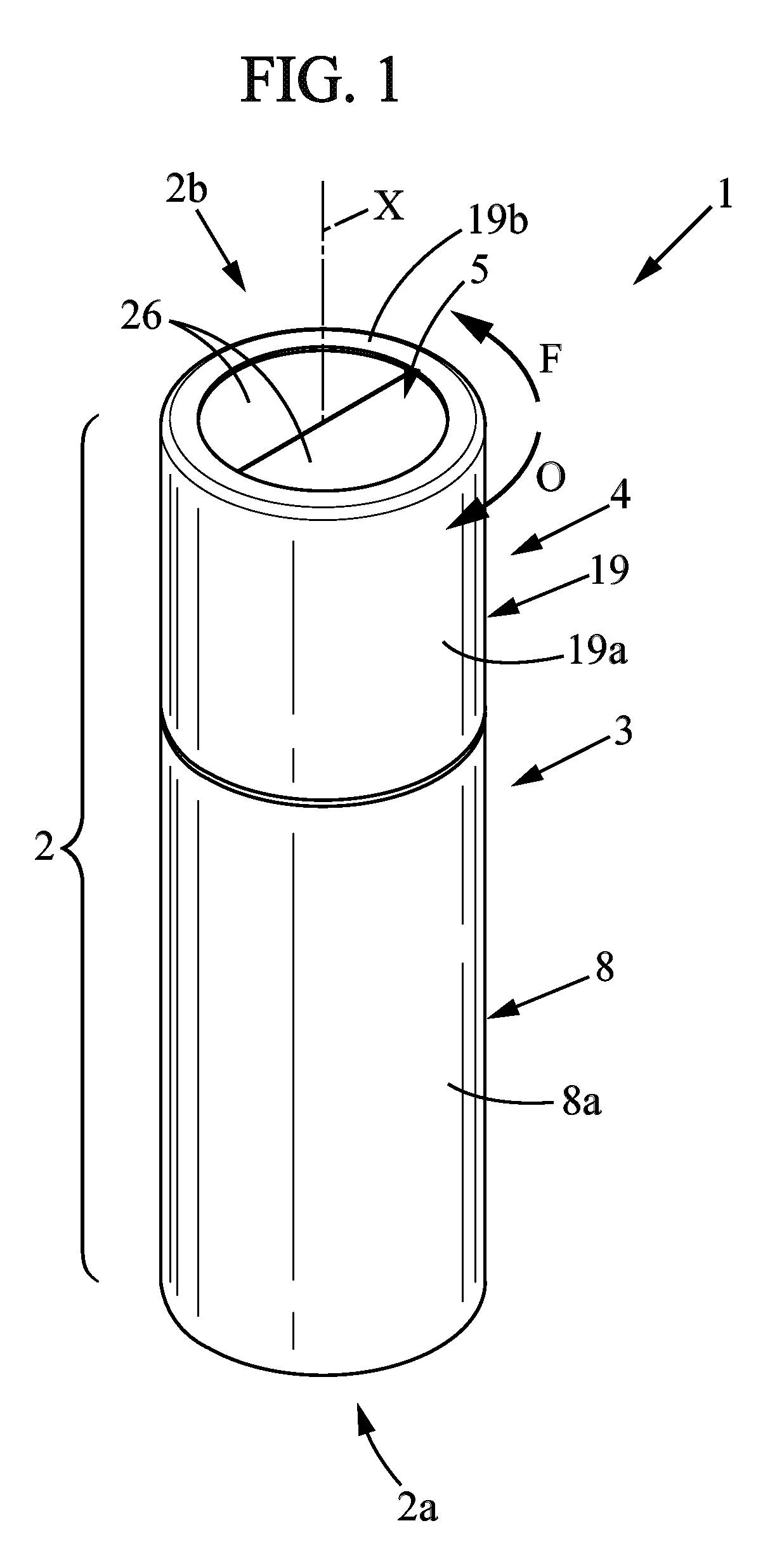
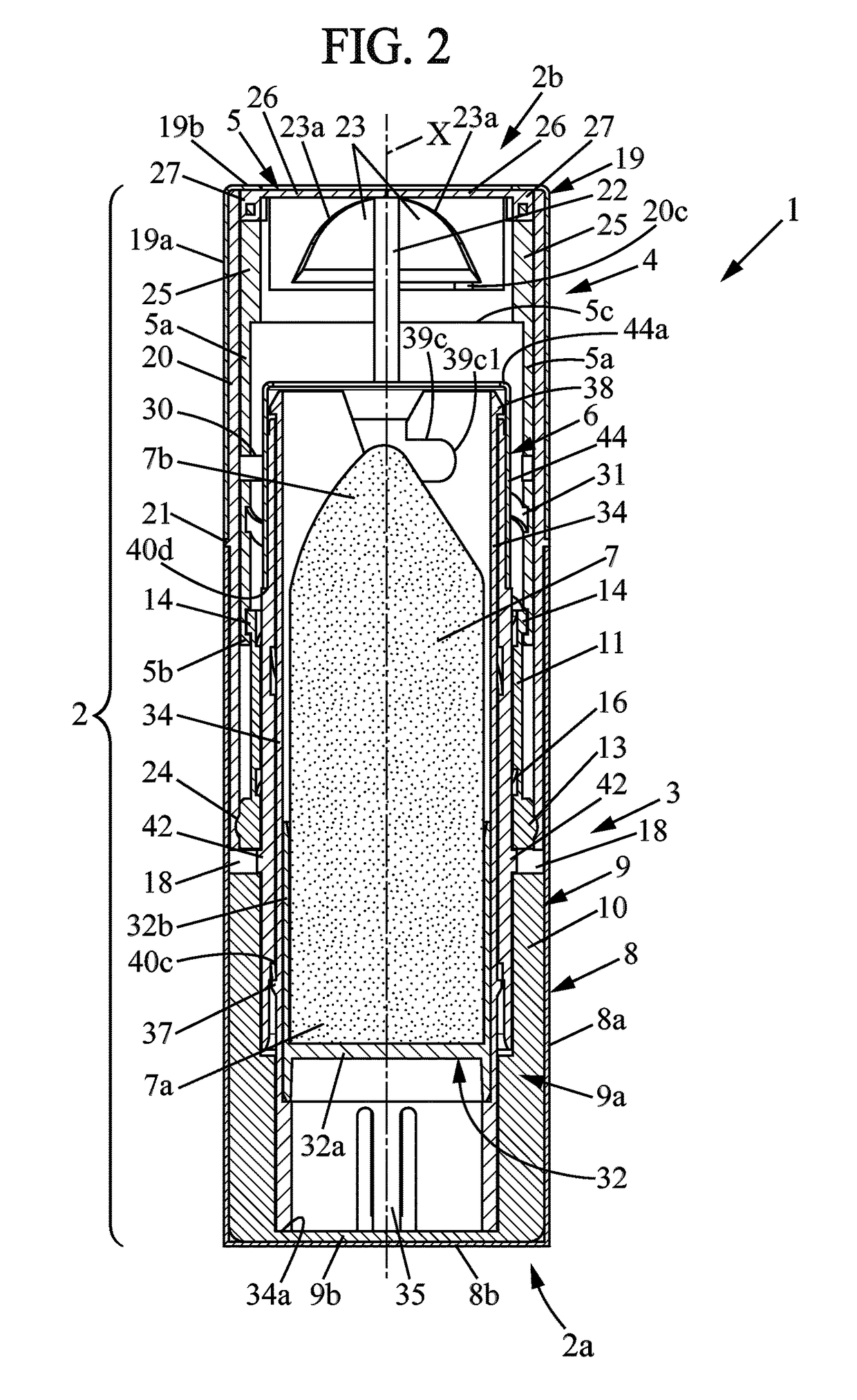
[0055]As can be seen in FIGS. 1, 2, 3, 3A, 4, 4A, the applicator device 1 comprises a tubular casing 2 which extends along a longitudinal direction X between first and second ends 2a, 2b, respectively the lower and upper ends in the current usage position of the applicator device (in the following, the terms “lower” and “upper” will be used with reference to this current usage position of the applicator device). More specifically, the tubular casing 2 may have a general cylindrical shape centered on a longitudinal axis X. The second end 2b is open.

[0056]The tubular casing 2 comprises a tubular base 3 extending along the longitudinal axis X and a sleeve 4 mounted so as to rotate freely on the tubular base 3 about the longitudinal axis X, between first and second angular positions respectively corresponding to the storage position (FIG. 1) and to the usage position (FIG. 7).

[0057]In the storage position, the second end 2b of the casing is closed by ...

second embodiment

B. Second Embodiment of the Invention

[0123]The second embodiment of the invention, shown in FIGS. 9 to 20, has many points in common with the first embodiment of the invention and will therefore not be fully described below. Only the differences of this second embodiment from the first embodiment described above will be detailed below, it being understood that the advantages already described for the first embodiment are retained in the second embodiment.

[0124]As can be seen in FIGS. 9 to 12, the applicator device 101 of the second embodiment comprises a tubular casing 102 which extends along a longitudinal direction X between first and second ends 102a, 102b, respectively the lower and upper ends. As in the first embodiment, the tubular casing 102 may have a general cylindrical shape centered on a longitudinal axis X, and the second end 102b is open.

[0125]The tubular casing 102 comprises a tubular base 103 extending along the longitudinal axis X and a sleeve 104 mounted so as to ro...


PUM


Abstract

An applicator device comprising a tubular base, a sleeve mounted rotating on the tubular base between a storage position and a use position, an end cover designed to close the sleeve, a maneuvering mechanism comprising first and second parts rotatably mounted relative to each other, and a cup carrying a stick of product, the first and second parts being driven in rotation respectively with the tubular base and the sleeve and being designed to move the cup axially when the sleeve rotates on the tubular base. The first and second parts of the maneuvering mechanism are mounted axially sliding respectively relative to the tubular base and to the sleeve, and are moved axially in the outlet direction of the stick of product when the sleeve is rotated towards the storage position from an intermediate angular position.

Description

CROSS-REFERENCE TO RELATED APPLICATION[0001]This Application is a 35 USC §371 US National Stage filing of International Application No. PCT / FR2014 / 052647 filed on Oct. 17, 2014, and claims priority under the Paris Convention to French Patent Application No. 13 60190 filed on Oct. 18, 2013.FIELD OF THE DISCLOSURE[0002]Field of the Invention[0003]The present invention relates to applicator devices for products in stick form and to their uses.[0004]Background of the Disclosure[0005]More particularly, the invention relates to an applicator device for a product, comprising:[0006]a tubular casing extending along a longitudinal axis between first and second ends, the second end being open, said casing being adapted to contain a stick of product and comprising:[0007]a tubular base extending along the longitudinal axis,[0008]a sleeve mounted so as to rotate freely on the tubular base about the longitudinal axis, between first and second angular positions,[0009]an end cover means adapted to c...

Claims


Application Information

Patent Timeline
Patent Type & Authority Patents(United States)
IPC IPC(8): A45D40/06A45D40/12A45D40/22
CPCA45D40/065A45D40/22A45D40/221A45D40/12
Inventor HERMOUET, YANNICKJOULIA, PIERRE
Owner PARFUMS CHRISTIAN DIOR
Why Eureka
Try Eureka