
Temperature controller for semiconductor wafer and temperature control method for semiconductor wafer

a technology of temperature controller and semiconductor wafer, which is applied in the direction of process and machine control, computer control, instruments, etc., can solve the problems of lowering control performance and inability to provide further compensation

Active Publication Date: 2017-10-24
KELK LTD
View PDF17 Cites 263 Cited by
  • Summary
  • Abstract
  • Description
  • Claims
  • Application Information

AI Technical Summary

Benefits of technology

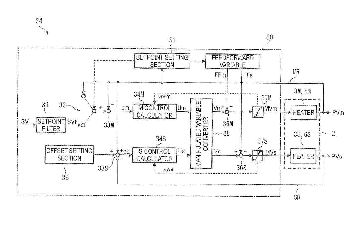
This patent text describes a temperature control system for semiconductor wafers that ensures consistent control across multiple loops and allows temperature adjusters to quickly respond to changes. The system includes a manipulated variable converter that reduces interference between different control loops. The technical effects of this invention are improved temperature control accuracy and efficiency for semiconductor wafers during processing.

Problems solved by technology

However, the techniques disclosed in Patent Literatures 1 and 2 have a problem of lowering a control performance because when the temperature adjusters (an actuator) undergo saturation in the process of responding to the setpoint, further compensation is unavailable.

Method used


Image

  • Temperature controller for semiconductor wafer and temperature control method for semiconductor wafer
  • Temperature controller for semiconductor wafer and temperature control method for semiconductor wafer
  • Temperature controller for semiconductor wafer and temperature control method for semiconductor wafer

Examples


first exemplary embodiment

[3] Effects of First Exemplary Embodiment

[0091]FIG. 4 shows setpoint responses through a single-input single-output system. FIG. 4(A) shows a temporal variation of the control variable PV and FIG. 4(B) shows a temporal variation of the manipulated variable MV.

[0092]In setpoint response through a control system in which the heaters 3M could be saturated, the control setpoint SV can be reached in the shortest time by: saturating the heaters 3M with a manipulated variable ff1, which enables the maximum output of the heaters 3M, so that the temperature is increased at the maximum speed; switching the manipulated variable to zero before the control setpoint SV is reached (the manipulated variable may be set at a minus in the case of using a thermoelectric element capable of heating and cooling); letting the control setpoint SV be automatically reached (the control setpoint SV may be reached with a braking force in the case of a minus manipulated variable); and finally immediately switchi...

second exemplary embodiment

[4] Second Exemplary Embodiment

[0112]Next, a second exemplary embodiment of the invention will be described. It should be noted that, in the following description, parts and the like identical to those described above are attached with the same reference signs and the explanation thereof is omitted.

[0113]In the first exemplary embodiment, when the temporary setpoint X is reached, the manipulated variable is immediately switched from the feedforward variable ff1 to the feedforward variable ff2 as shown in FIG. 5.

[0114]In contrast, the second exemplary embodiment is different from the first exemplary embodiment in that the manipulated variable is switched as shown in FIG. 7.

[0115]Specifically, in the second exemplary embodiment, the range A is further divided into a plurality of ranges and feedforward variables are switched in accordance with these ranges to achieve a further minute control as shown in FIG. 7(B). The second exemplary embodiment is different from the first exemplary em...


PUM


Abstract

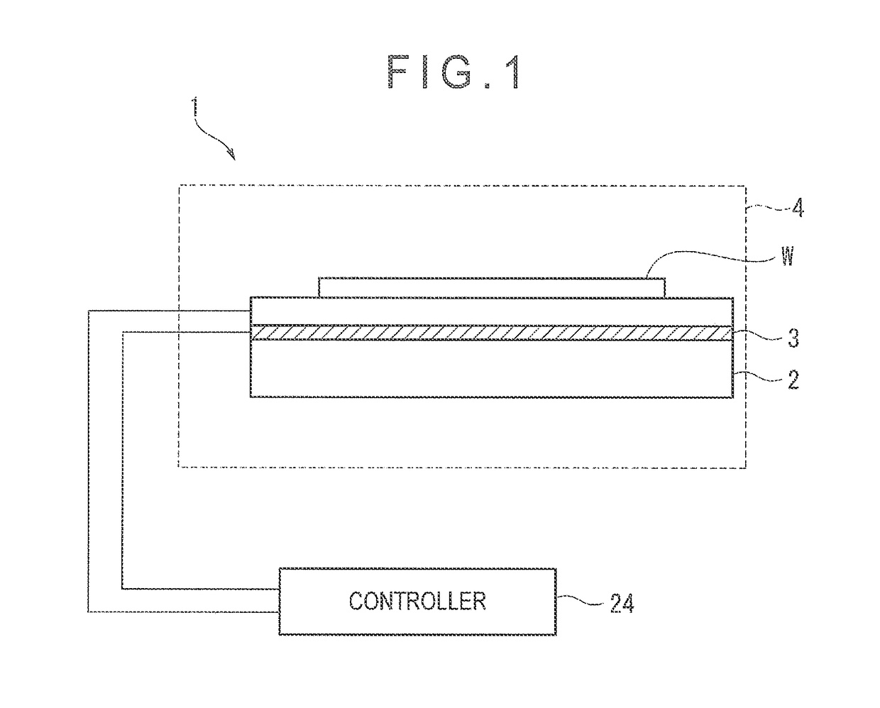
A temperature controller that performs a temperature control on a plurality of temperature adjusters including a reference temperature adjuster to adjust a temperature of a semiconductor wafer includes a setpoint setting section that: sets a temperature detected by a master temperature detector as a control setpoint for a reference one of the temperature adjusters of a master loop, until a temporary setpoint below an actual control setpoint preset as a desired temperature of the semiconductor wafer is reached; and sets the actual control setpoint as the control setpoint for the master loop after the temporary setpoint is reached.

Description

[0001]The entire disclosure of Japanese Patent Application No. 2014-012293 filed Jan. 27, 2014 is expressly incorporated herein by reference herein.TECHNICAL FIELD[0002]The present invention relates to a temperature controller for a semiconductor wafer and a temperature control method for a semiconductor wafer that are configured to perform a temperature control on a plurality of temperature adjusters to adjust the temperature of the semiconductor wafer.BACKGROUND ART[0003]A process for treating a semiconductor wafer such as a silicon wafer includes controlling the in-plane temperature distribution of the silicon wafer as desired while controlling the temperature of the silicon wafer to a temperature setpoint.[0004]For instance, according to a known method, heaters are each incorporated in an independent control loop so that the semiconductor wafer is simultaneously heated using a plurality of temperature adjusters.[0005]Regarding the above temperature control for a semiconductor wa...

Claims


Application Information

Patent Timeline
Patent Type & Authority Patents(United States)
IPC IPC(8): G05D23/00G05D23/19H01L21/67G05B15/02
CPCG05B15/02H01L21/67248G05D23/1934
Inventor MIMURA, KAZUHIRO
Owner KELK LTD
Learn More