Electromagnetic drive coil unit and molding method thereof

a technology of drive coil and magnet, which is applied in the direction of magnets, windings, magnetic bodies, etc., can solve the problems of increasing costs, and achieve the effects of preventing breaking of stator coils, waterproof properties, and strong attachmen

Active Publication Date: 2017-10-17
FUJIKOKI CORP
View PDF18 Cites 1 Cited by
  • Summary
  • Abstract
  • Description
  • Claims
  • Application Information

AI Technical Summary

Benefits of technology

[0020]By preparing plural types of connector frame members to correspond to opposite connectors, it is possible to manufacture various molded coil units without changing a molding die.
[0022]It is possible to prevent a liquid such as water from invading into the electromagnetic drive coil unit using the molded portion and to prevent bubbles from being generated in the molded portion. Accordingly, it is possible to provide an electromagnetic drive coil unit with waterproof properties and strength secured.
[0023]Since the inner molding process is performed using a dwelling process at a low pressure, it is possible to prevent breaking of the stator coil which is installed in the stator assembly and which can be relatively easily broken with an external pressure. On the other hand, since the inner molded portion formed through the inner molding process is formed in the dwelling process at a low pressure in consideration of the breaking of the stator coil or the like, it may be difficult to secure satisfactory strength due to formation of a void or the like. However, since the molded portions of the outer circumference of the stator assembly having the inner molded portion and the outer circumference of the power supply terminal molded in a resin material supplied to perform the inner molding process are covered with an outer molded portion, a double-molded structure is provided in which the inner molded portion is covered with the outer molded portion and it is thus possible to satisfactorily enhance the strength of the portion molded through the dwelling process at a low pressure.

Problems solved by technology

Since a fitting dimension of the connector to the opposite connector is strictly required, it is necessary to strictly manage the dimensional accuracy of the molding die, thereby causing an increase in cost.

Method used


Image

  • Electromagnetic drive coil unit and molding method thereof
  • Electromagnetic drive coil unit and molding method thereof
  • Electromagnetic drive coil unit and molding method thereof

Examples


first embodiment

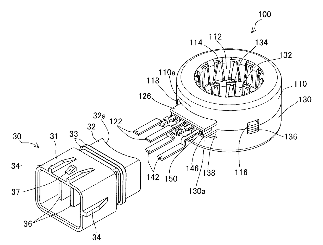
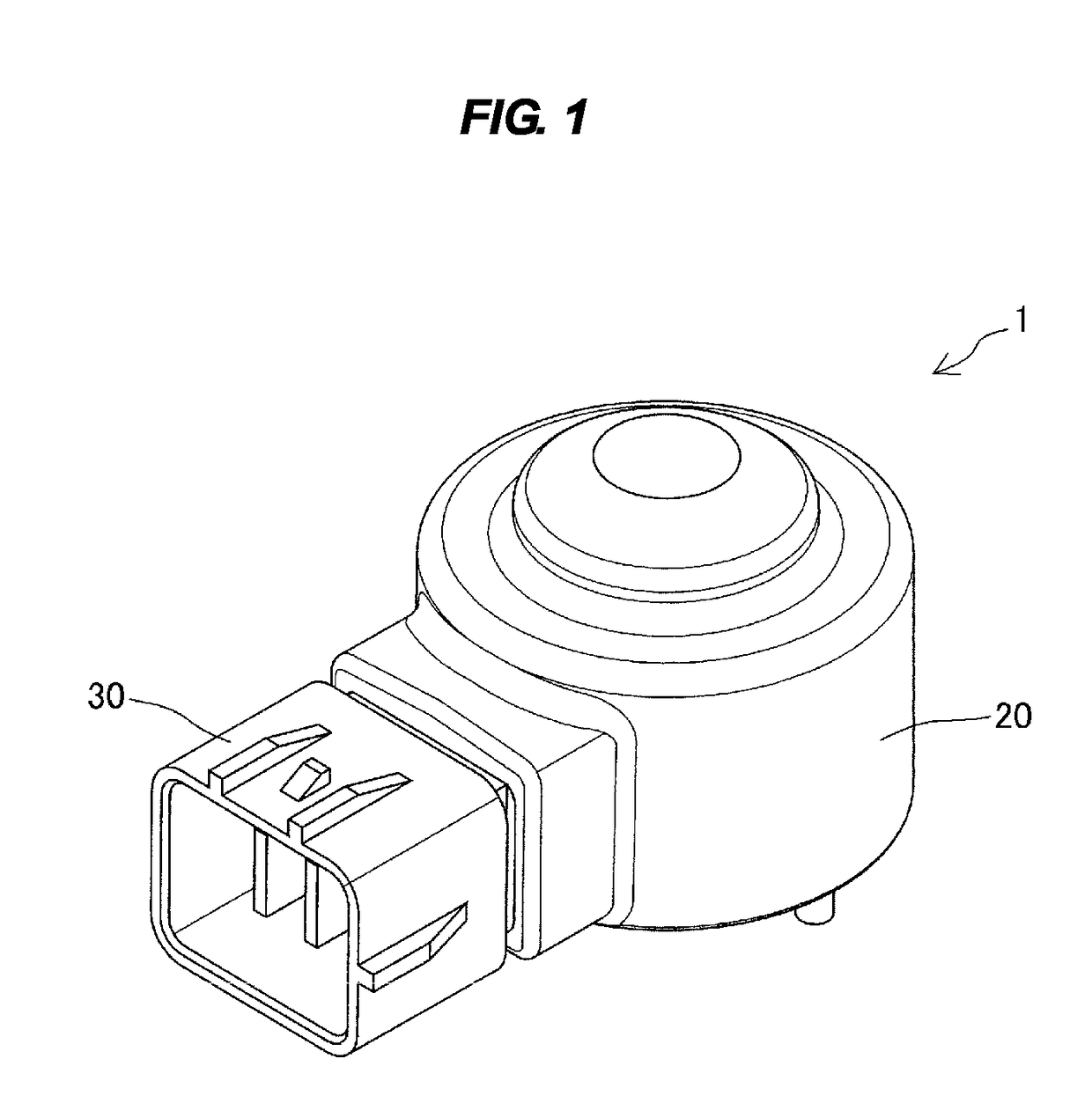
[0033]In an electromagnetic drive coil unit 1 according to a first embodiment of the invention, as illustrated in FIG. 1, a resin mold 20 is formed after power supply terminals 122 and 142 (FIG. 2) are inserted into a connector frame member 30 which has been molded in advance. Accordingly, a stator assembly having a complicated structure and the connector frame member requiring accurate molding can be formed using separate molds.

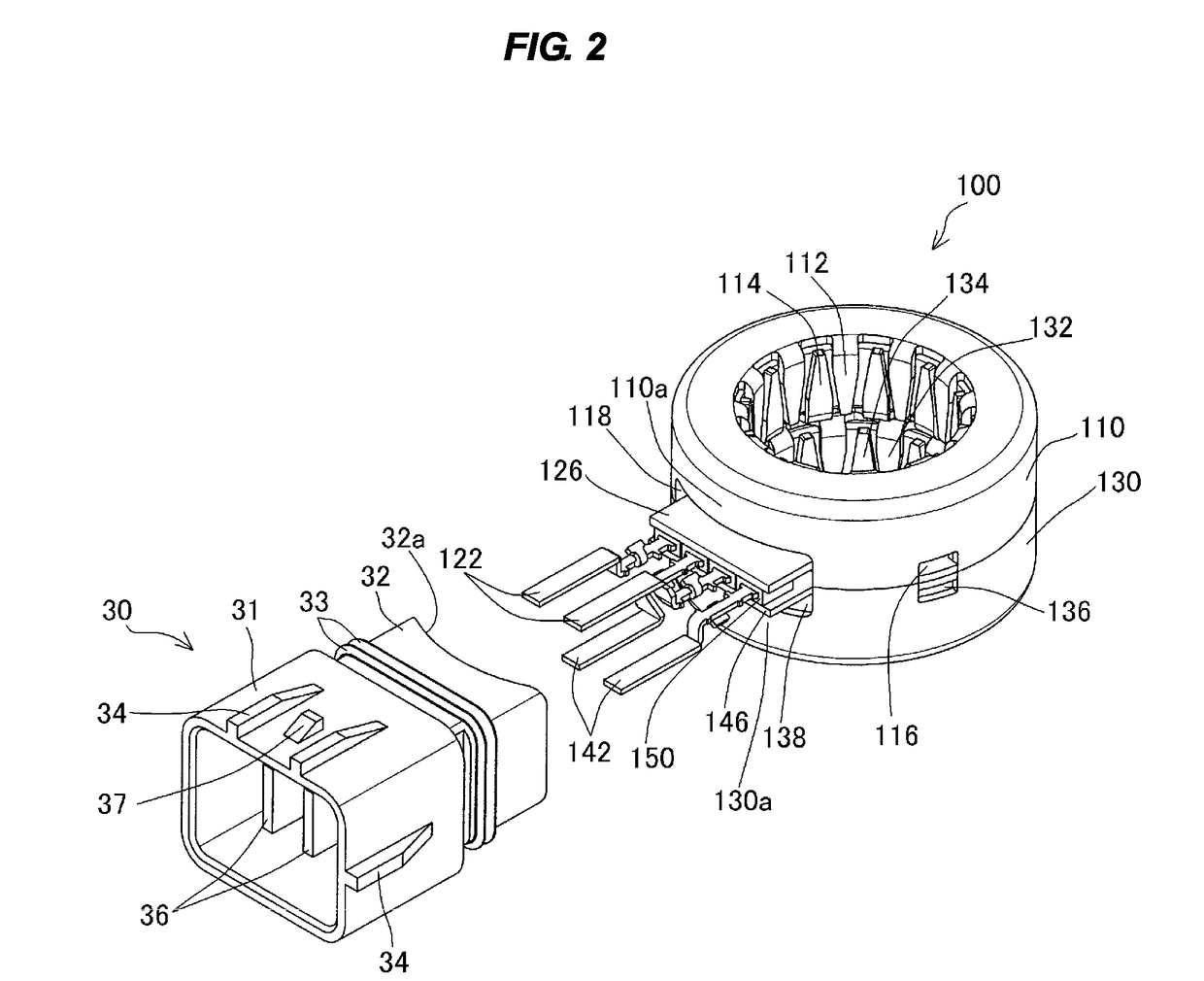
[0034]More specifically, as in the component structure illustrated in FIG. 2, the connector frame member 30 is prepared as a separate member, which has been molded in a separate process in advance, with respect to a stator assembly 100.

[0035]The connector frame member 30 which has been molded through a separate process in advance is a resin member and includes a connector portion 31 and a coupling portion 32. The coupling portion 32 has an edge portion 32a which comes in close contact with the outer circumferences of an upper yoke 110 and a lower yoke 130 of...

second embodiment

[0056]An electromagnetic drive coil unit 1b (FIG. 8) according to a second embodiment of the invention includes a stator assembly 300 and a connector portion 304 surrounding a power supply terminal 303, and an outer guide portion 305 and a stopper protrusion 306 for locking a plug are formed on the outer circumferential surface of the connector portion 304 which the plug (not illustrated) is attached to and detached from.

[0057]As illustrated in FIG. 7, the stator assembly 300 is provided with an upper yoke 307 and a lower yoke 308 which have a cylindrical shape and which are arranged to face each other, and includes an upper bobbin 310 on which a stator coil309 is wound (FIG. 6) and a lower bobbin 312 on which a stator coil 311 is wound so as to correspond to the upper yoke 307 and the lower yoke 308. The upper yoke 307 and the lower yoke 308 have the same shape, the upper bobbin 310 and the lower bobbin 312 have the same shape, and inner yokes 321 (to be described later) disposed t...


PUM

PropertyMeasurementUnit
circumferenceaaaaaaaaaa
pressureaaaaaaaaaa
shapeaaaaaaaaaa

Abstract

A method of molding an electromagnetic drive coil unit is provided which can secure satisfactory strength and waterproof properties. In a method of molding an electromagnetic drive coil unit in which a stator assembly includes bobbins having stator coils wound thereon and yokes in which an inner yoke having magnetic pole teeth and an outer yoke having magnetic pole teeth are combined and in which the stator assembly and a power supply terminal supplying power to the bobbins are molded in a resin, an inner molding process is performed on the inside of the outer yoke in a state where ends of the stator coils of the stator assembly are connected to the power supply terminal and an outer molding process is performed to cover an outer circumference of the stator assembly having an inner molded portion and an outside of the power supply terminal after the inner molding process.

Description

BACKGROUND OF THE INVENTION1. Field of the Invention[0001]The present invention relates to an electromagnetic drive coil unit which is provided as an actuator in an electric valve or an electromagnetic valve and a molding method thereof.2. Description of the Related Art[0002]As an example of a resin-sealing structure of such a type of electromagnetic drive coil unit, Japanese Patent Application Laid-open No. 2010-106796 discloses a stepping motor which includes a stator including a coil, a magnet rotor installed in the stator, and an output shaft fixed to the center of the magnet rotor and in which the coil or the magnet rotor is molded and covered with a resin casing and a connector protruding from the casing is formed integrally in the casing.[0003]Japanese Patent Application Laid-open No. 8-65994 discloses an example in which a stator coil of a stepping motor which is provided as a molded coil includes first and second outer yokes having plural magnetic pole teeth formed to protr...

Claims


Application Information

Patent Timeline
Patent Type & Authority Patents(United States)
IPC IPC(8): H01F7/128H02K5/08H02K5/22H02K15/12H01F7/06H02K37/14H02K3/52
CPCH01F7/128H02K5/08H02K5/225H02K15/12H01F2007/062H02K3/525H02K37/14
Inventor ARAI, YUSUKEHOSOYA, TAKESHI
Owner FUJIKOKI CORP
Why Eureka
Try Eureka