Solid state lighting panel

a lighting panel and solid-state technology, applied in the direction of semiconductor lamp usage, electronic switching, pulse technique, etc., can solve the problems of reducing power efficiency, affecting the longevity of streets, and affecting the downstream components of lighting devices, so as to reduce the amount of audible noise, reduce the surge load of the power grid, and maximize the longevity of streets

Active Publication Date: 2017-10-10
HEARTLAND INC
View PDF4 Cites 4 Cited by
  • Summary
  • Abstract
  • Description
  • Claims
  • Application Information

AI Technical Summary

Benefits of technology

The present invention provides a solid state lighting panel that solves inadequcies of the prior art. The panel comprises a programmable logic circuit and a plurality of solid state relay devices which are in electrical communication with a plurality of solid state lighting devices. The programmable logic circuit is programmed to sequentially energize the solid state relay devices, which in turn at the next zero crossing point of the sinusoidal input line voltage to the lighting panel, energizes the solid state lighting devices. The invention aims to maximize the longevity of LED lighting fixture components, reduce surge loading of the power grid, peak current drawn by an LED lighting installation, and audible and electrical noise produced by the panel. It also provides a combination of staggered imitation, zero-cross initiation, and soft start of LED light illumination, as well as surge protection for the solid state components within a street-side cabinet and manual overrides in case of failure of one or more automatic control devices.

Problems solved by technology

If these lighting devices are energized simultaneously, this may cause a sudden spike of so-called “inrush current” which may be harmful not only to the panel but also to the upstream power line source and the downstream lighting devices as well.
Although inrush current typically reduces to a lower steady-state device current during continued normal device operation, the effect of significant inrush current can be highly detrimental to downstream components.
For example, inrush currents can generate undesirable EMI / RFI, damage device components, lower supply voltage available to other circuits, decrease power efficiency, cause system errors, make devices difficult to control, and complicate device design.
For example, if the input power source for a device is current limited or has poor load regulation, large inrush currents can cause the input voltage to drop significantly, thereby affecting overall device operation.
In addition to downstream devices and apparatus being adversely affected, the upstream power line source may also be adversely affected.
Large and sudden increases in load may reduce the voltage across an entire power line or power distribution circuit.
Furthermore, when this type of load occurs simultaneously in many areas, such as when darkness sets in and street lights are turned on around an entire region, even the power plant may find it difficult to maintain both proper frequency and voltage on the AC power lines.
While many devices are subject to problematic inrush currents, some types of motors, many types of traditional lighting, power converters, and power supplies often have particularly elevated inrush currents.

Method used


Image

  • Solid state lighting panel
  • Solid state lighting panel
  • Solid state lighting panel

Examples


Embodiment Construction

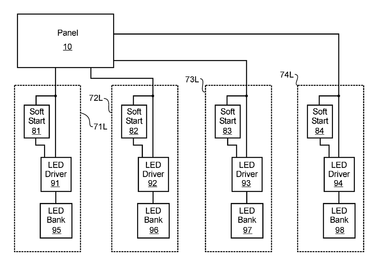
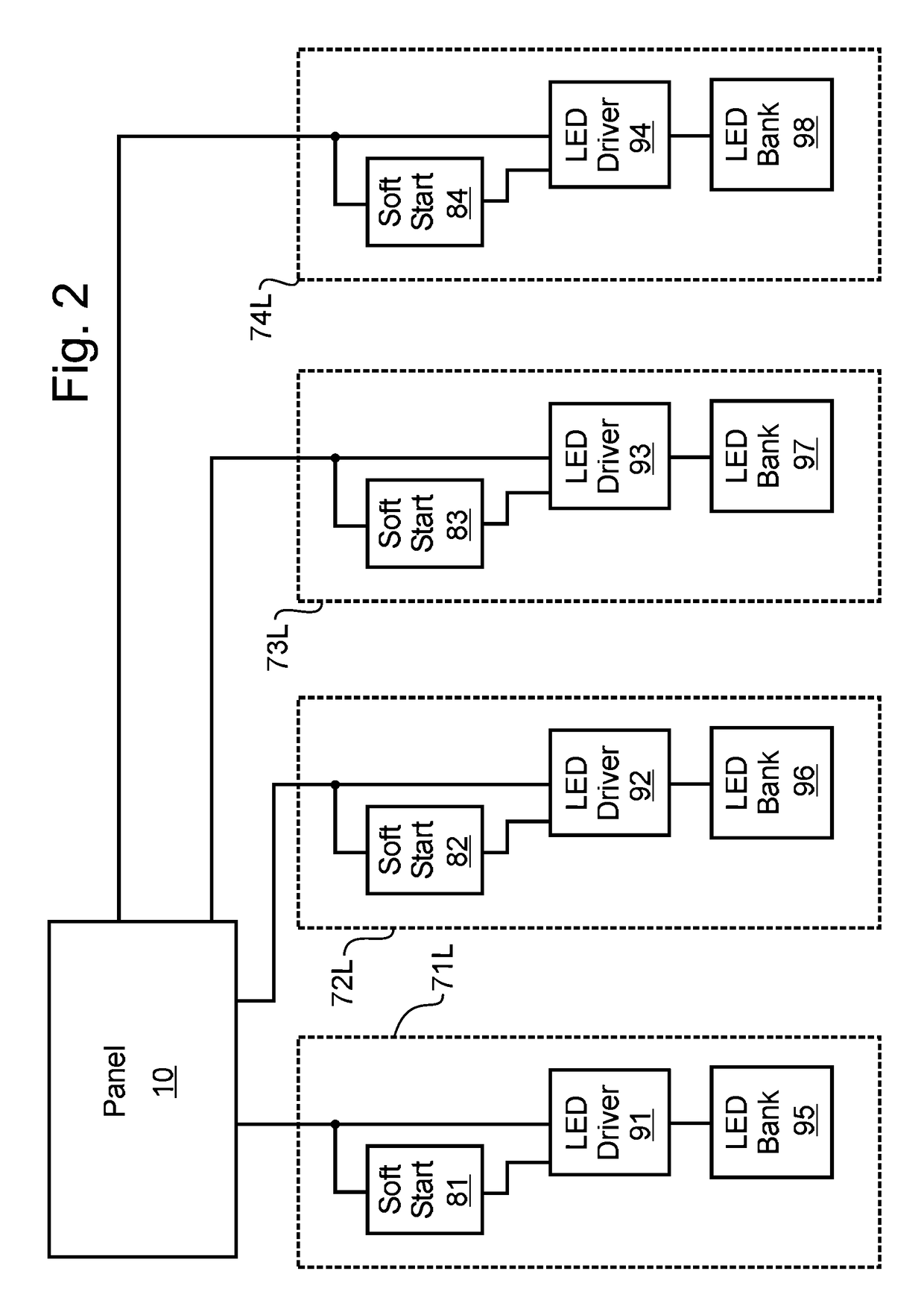
[0020]Manifested in the preferred embodiment, the present invention provides a solid state lighting panel incorporating the ability to soft start and autonomously dim LED based lighting devices.

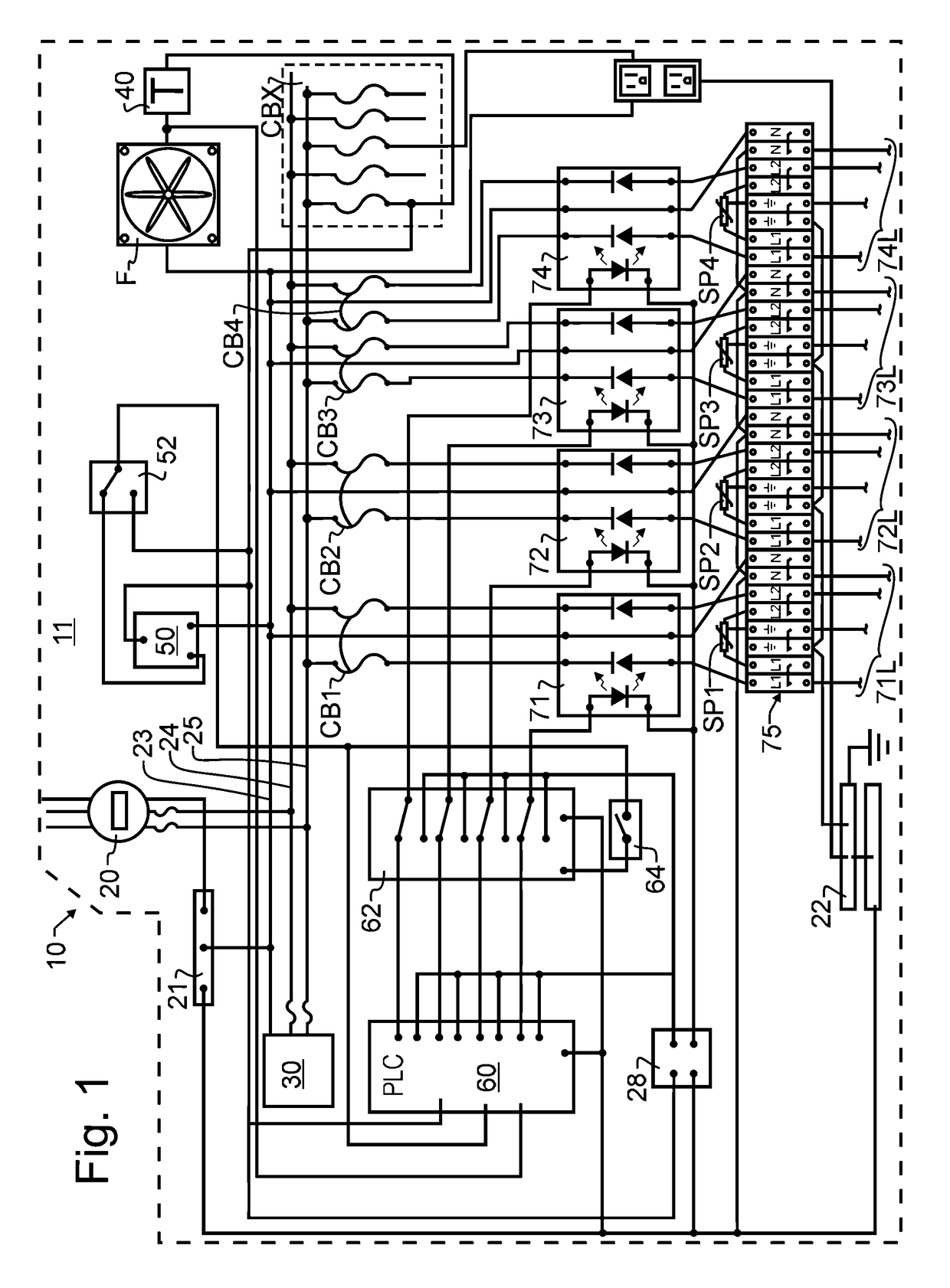
[0021]A preferred embodiment solid state lighting panel 10 in accordance with the present invention is depicted schematically in FIG. 1. As illustrated, incoming AC line power 20 may include a pair of circuit breakers and an optional power meter, and may be connected to any suitable power line or other power source. The AC power line 20 will typically be a 240 VAC source as illustrated, though it will be understood herein that in alternative embodiments other voltages and other arrangements of power lines may be provided without deviating from the teachings of the present invention.

[0022]The incoming neutral line will be connected to neutral bus 21 and from there to neutral bus 22 and to neutral distribution line 23. Neutral bus 22 further provides connection to each of the neutral connection...


PUM


Abstract

A solid state lighting panel sequentially energizes a plurality of LED lighting banks at the zero crossing points of the sinusoidal input line voltage. Each LED lighting bank is provided with a soft start circuit to ramp up the luminous intensity gradually. The energizing of one LED lighting bank at a time at zero cross, in combination with soft start ramp, keeps inrush spikes below the ultimate steady state operating current level. The lighting panel is further provided with line-in and line-out surge protection, along with a specific arrangement of terminals within a terminal block, the provision of surge protectors therein, the use of optically isolated solid state relays, and a plurality of well-placed circuit breakers to provide enhanced surge tolerance.

Description

CROSS REFERENCE TO RELATED APPLICATIONS[0001]The present application claims the benefit of U.S. provisional patent application 62 / 387,967 filed Jan. 11, 2016 of like title and inventorship, and also claims the benefit of U.S. provisional patent application 62 / 386,494 filed Dec. 3, 2015 of like inventorship, the teachings and entire contents of each which are incorporated herein by reference.BACKGROUND OF THE INVENTION[0002]1. Field of the Invention[0003]The present invention is directed generally to industrial and commercial lighting control panels, and more particularly to solid state lighting panels such as are commonly mounted in cabinets and that are capable of sequentially energizing a plurality of LED lighting panels at the zero crossing points of the sinusoidal input line voltage and ramping up luminous intensity within each panel or group of co-powered panels.[0004]2. Description of the Related Art[0005]Lighting panels are a common device found in every mid to large scale co...

Claims


Application Information

Patent Timeline
Patent Type & Authority Patents(United States)
IPC IPC(8): H05B33/00H05B33/08H03K17/94H05B44/00H05B45/50
CPCH05B33/089H03K17/941H05B33/0845H05B33/0821H05B45/50H05B45/10Y02B20/30
Inventor REDFIELD, BLAKE D.
Owner HEARTLAND INC
Why Eureka
Try Eureka