Mode division multiplexed passive optical network (MDM-PON) apparatus, and transmission and reception method using the same

a passive optical network and multiplexing technology, applied in the field of passive optical communication, can solve the problems of many losses, increased so as to reduce significantly increase the loss in the optical power splitter

Inactive Publication Date: 2017-10-10
ELECTRONICS & TELECOMM RES INST
View PDF5 Cites 1 Cited by
  • Summary
  • Abstract
  • Description
  • Claims
  • Application Information

AI Technical Summary

Benefits of technology

[0008]Provided is a structure of a passive optical network apparatus, which may reduce the loss in the optical power splitter of a general TDM-PON, particularly solving the problem that loss in the optical power splitter significantly increases with a splitting ratio.

Problems solved by technology

However, in the TDM-PON, loss occurs in the optical power splitter and the loss in the optical power splitter increases with a splitting ratio.
Such loss in the optical power splitter causes many losses, such as a loss of a Feeder line and a loss in a power budget of an OLT / ONU.
For this reason, there is a difficulty in increasing the number of subscribers and the length of a Feeder line.

Method used


Image

  • Mode division multiplexed passive optical network (MDM-PON) apparatus, and transmission and reception method using the same
  • Mode division multiplexed passive optical network (MDM-PON) apparatus, and transmission and reception method using the same
  • Mode division multiplexed passive optical network (MDM-PON) apparatus, and transmission and reception method using the same

Examples


Embodiment Construction

[0024]Hereinafter, exemplary embodiments of the present disclosure will be described with reference to the accompanying drawings. In the following description, terms used throughout this specification are defined in consideration of the functions according to exemplary embodiments, and can be varied according to a purpose of a user or manager, or precedent and so on. Unless otherwise defined, all technical and scientific terms used herein have the same meaning as is commonly understood by one of skill in the art to which this invention belongs at the time of filing. If specifically defined, then the meanings of the terms used in the following embodiments shall follow the definitions.

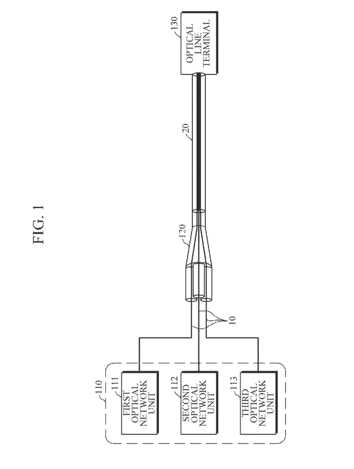
[0025]FIG. 1 is a diagram illustrating an example of a Mode Division Multiplexed Passive Optical Network (MDM-PON) apparatus 100 according to an exemplary embodiment.

[0026]Referring to FIG. 1, the MDM-PON apparatus 100 includes three or more optical network units (ONUs) 110, a non-mode selective multiple...


PUM


Abstract

A Mode Division Multiplexed Passive Optical Network (MDM-PON) apparatus includes: a non-mode selective multiplexer which includes a first end where three or more single-mode optical fibers are spaced apart from each other by a predetermined distance, and a second end where cores of the three or more single-mode optical fibers are tapered such that a gap between the three or more single-mode optical fibers is narrower than the predetermined distance while the three or more single-mode optical fibers are spaced apart from each other by an equal distance; an optical line terminal (OLT) which is connected to the second end through a few-mode fiber, and transmits a downstream optical signal; and three or more optical network units (ONUs) which is connected to the first end through the three or more single-mode optical fibers, and transmits upstream optical signals.

Description

CROSS-REFERENCE TO RELATED APPLICATION(S)[0001]This application claims priority to Korean Patent Application No. 10-2015-0127928, filed on Sep. 9, 2015, in the Korean Intellectual Property Office, the entire disclosure of which is incorporated herein by reference for all purposes.BACKGROUND[0002]1. Field[0003]The following description generally relates to a technology for passive optical communication, and more particularly to a passive optical network apparatus using mode-division multiplexing.[0004]2. Description of the Related Art[0005]A Passive Optical Network (PON) apparatus is composed of an optical line terminal (OLT) of a communication service provider side, an optical network unit (ONU) of a subscriber side, and optical cables and an optical distribution network that connect the OLT and the ONU.[0006]In the Time Division Multiplexing (TDM), which is a multiplexing method used by a passive optical network apparatus, a downstream optical signal, output from an OLT, is split b...

Claims


Application Information

Patent Timeline
Patent Type & Authority Patents(United States)
IPC IPC(8): H04B10/27H04B10/2581H04B10/25H04B10/2587H04J14/08H04B10/272
CPCH04B10/27H04B10/2504H04J14/08H04B10/272H04B10/2581H04B10/2587H04B10/25H04J14/04H04B10/25891
Inventor CHANG, SUN HYOKKIM, KWANG JOONLEE, HYUN JAEHAN, CHAN GYO
Owner ELECTRONICS & TELECOMM RES INST
Why Eureka
Try Eureka