
Electrical plug connector

a plug-in connector and plug-in technology, applied in the direction of coupling device connection, two-part coupling device, electrical apparatus, etc., can solve problems such as terminal bend damag

Active Publication Date: 2017-10-03
ADVANCED CONNECTEK INC
View PDF16 Cites 7 Cited by
  • Summary
  • Abstract
  • Description
  • Claims
  • Application Information

AI Technical Summary

Benefits of technology

The present invention provides an electrical plug connector that prevents damage to the terminals when the circuit board is inserted between the soldering portions. This is achieved by using a soldering portion with elasticity, which allows for easy insertion of the circuit board and prevents bending damage of the terminals due to position tolerance.

Problems solved by technology

Bending damage of the terminals occurs when the circuit board collides with the soldering portions due to the position tolerance of the terminals when the upper-row soldering portions and the lower-row soldering portions of the terminals are inserted between an upper surface and a lower surface of the circuit board.

Method used


Image

  • Electrical plug connector
  • Electrical plug connector
  • Electrical plug connector

Examples


Embodiment Construction

[0024]To make the purpose, the features, and advantages of this invention to be easier to be understood to those who has the general knowledge in this field, a preferred embodiment is recited in detail below with the accompanying drawings.

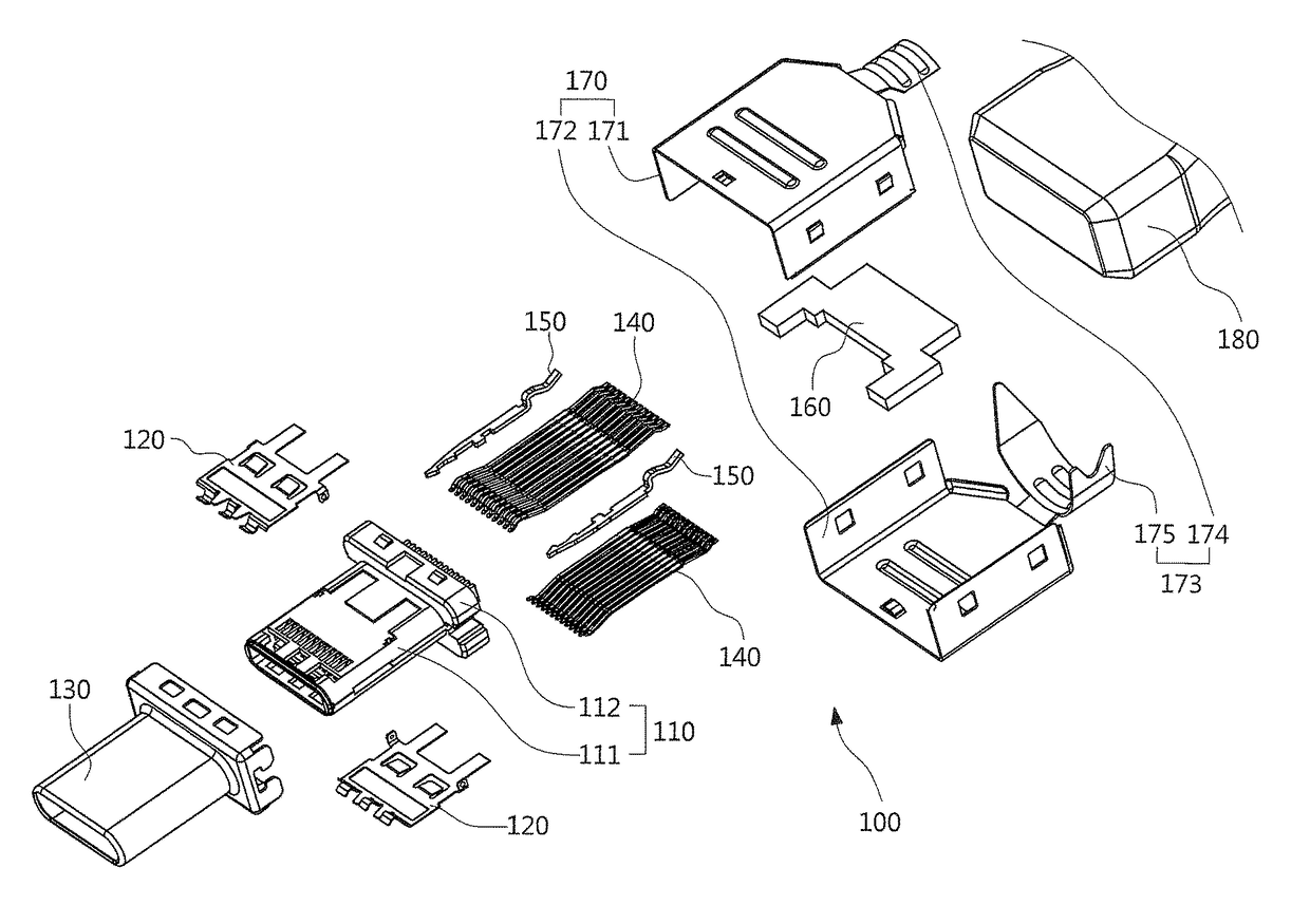
[0025]Please refer to FIGS. 1 and 2. FIG. 1 is a schematic diagram of a preferred embodiment of an electrical plug connector according to the present invention. FIG. 2 is an exploded diagram of a preferred embodiment of the electrical plug connector according to the present invention. The electrical plug connector 100 can be an Universal Serial Bus (USB) Type C connector, which conforms, but is not limited, to the USB Type-C Cable and Connector Specification, Version 1.0 RC4. The electrical plug connector 100 comprises an insulated housing 110, two metallic plates 120, a metallic shell 130, a plurality of terminals 140, a pair of latches 150, a circuit board 160, an auxiliary metallic shell 170, an overcoat 180, and wires (not shown). The insulated...


PUM


Abstract

An electrical plug connector includes an insulated housing, a metallic shell, two terminal sets, and a circuit board. The insulated housing includes a front portion and a rear portion. The front portion extends forwardly from the rear portion, and an inside of the front portion forms a receiving cavity. The metallic shell covers the insulated housing. Each terminal set is composed with a plurality of terminals. Each terminal includes a contact portion, a retaining portion, and a soldering portion. The retaining portion is retained in the insulated housing. The soldering portion extends backwardly from the retaining portion. The soldering portions are arranged as an upper row and a lower row in symmetry, and the soldering portion is of the spring arm type. The circuit board is inserted between the upper row and the lower row of the soldering portions. The upper row and the lower row of the soldering portions clip elastically the circuit board.

Description

BACKGROUND OF INVENTION[0001]1. Field of the Invention[0002]The present invention relates to an electrical connector and, more particularly, to an electrical plug connector.[0003]2. Description of Prior Art[0004]The conventional electrical plug connector includes an insulated housing, a plurality of terminals, and a circuit board. The front end of the insulated housing defines an opening and an insertion space therein. In other words, the insertion space which communicates with the opening is surrounded by the insulated housing. The terminals which are retained in the insulated housing are arranged in an upper row and a lower row. The front ends of the terminals are contact portions. The contact portions of the electrical plug connector are used to electrically contact with the plurality of terminals of the mating electrical receptacle connector. The contact portions are exposed in the insertion space and arranged in the upper row and the lower row, which are disposed in an upper in...

Claims


Application Information

Patent Timeline
Patent Type & Authority Patents(United States)
IPC IPC(8): H01R12/57H01R13/66H01R24/60H01R43/16H01R107/00
CPCH01R13/6658H01R12/57H01R24/60H01R43/16H01R2107/00
Inventor KAO, YA-FENTSAI, YU-LUNHOU, PIN-YUANLIAO, CHUNG-FUTSAI, WEN-HSIENCHEN, MAO-SHENG
Owner ADVANCED CONNECTEK INC
Learn More