
Double-nozzle injector capable of spraying evenly at medium and low pressure

a technology of medium and low pressure and evenly sprinkling fluid, which is applied in the direction of spray nozzles, spraying apparatus, spraying apparatus, etc., can solve the problems of poor evenness, unstable rotation of spraying fluid, poor evenness of spraying fluid under medium and low pressure, etc., and achieves stable work, simple structure, and reliable operation

Active Publication Date: 2017-09-26
JIANGSU UNIV
View PDF11 Cites 0 Cited by
  • Summary
  • Abstract
  • Description
  • Claims
  • Application Information

AI Technical Summary

Benefits of technology

The fluidic sprinkler with double nozzles ensures stable operation and even sprinkling at medium and low pressures, overcoming the limitations of instability and unevenness in existing single-nozzle designs by effectively controlling pressure differences and water distribution.

Problems solved by technology

The existing fluidic sprinkler is in a structural form of single nozzle, and has a key technical problem that the sprinkler cannot accomplish stable rotation caused by insufficient driving force due to insufficient obtained under a medium and low working pressure, and the sprinkling of a single nozzle further has a problem of poor evenness under a medium and low working pressure.
: 200710134562.5), all of the above are fluidic sprinklers with a single nozzle having problems that the sprinklers cannot work stably and have poor evenness under a medium and low pressure.
This application has the shortage that the water-intake signal nozzle is fixedly located above the outlet of the gasket, such that under a medium and low pressure, the water-intake signal nozzle cannot be adjusted to obtain signal water, and thus the sprinkler cannot accomplish rotation.
This application has the shortage that the shape, size, setting position of the cover plate are not defined, and under a medium and low pressure condition, it cannot be guaranteed that the fluidic sprinkler stably and reliably obtains the signal water and accomplishes rotation.

Method used


Image

  • Double-nozzle injector capable of spraying evenly at medium and low pressure
  • Double-nozzle injector capable of spraying evenly at medium and low pressure
  • Double-nozzle injector capable of spraying evenly at medium and low pressure

Examples


Embodiment Construction

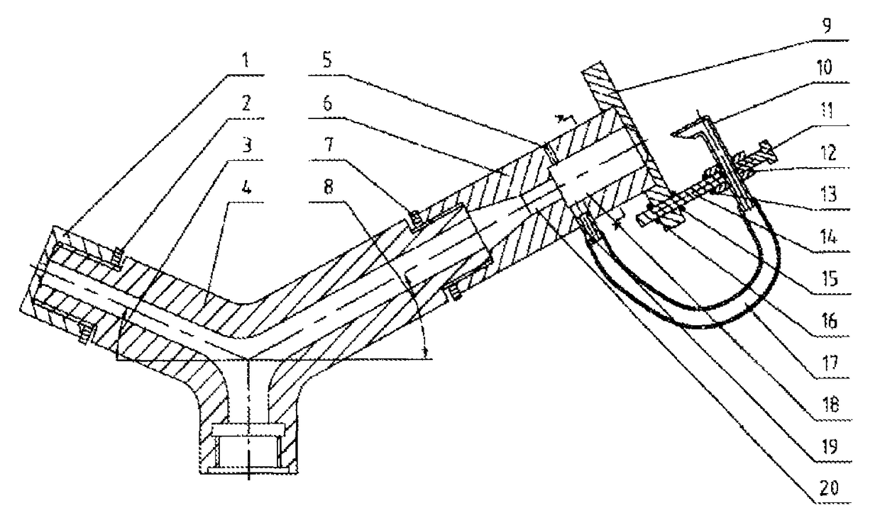
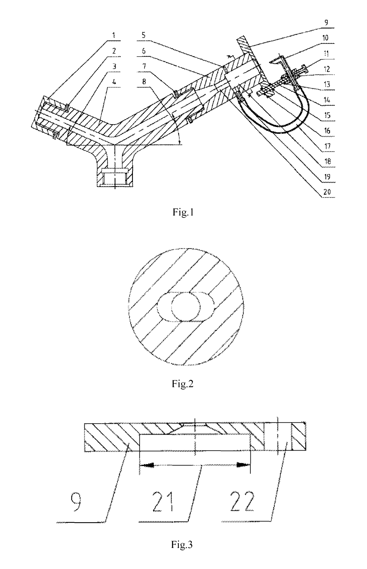
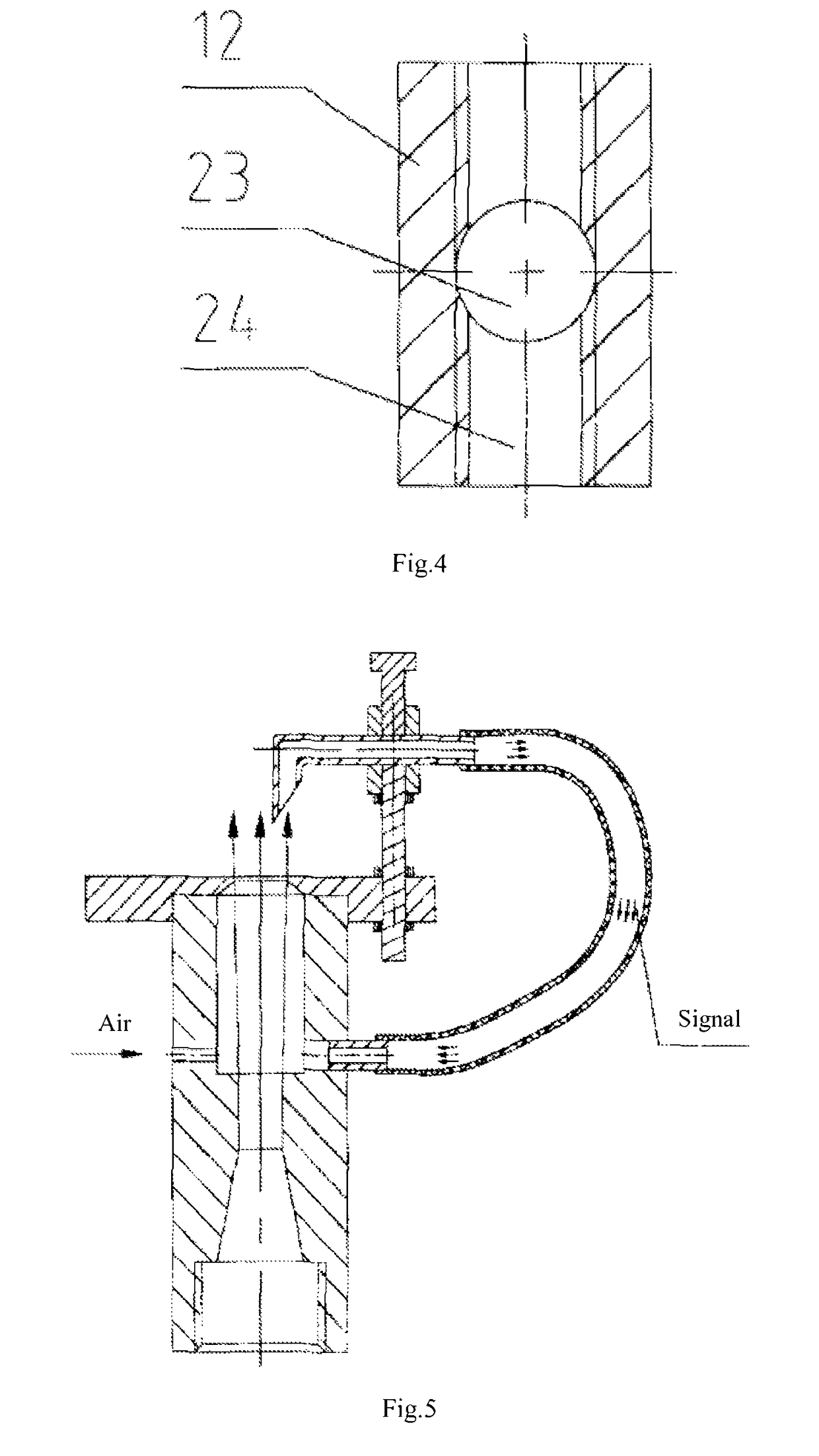
[0023]As shown in FIG. 1, the present invention includes a secondary nozzle 1, a secondary locknut 2, a sprinkler body 4, a fluidic element body 6, a primary locknut 7, a cover plate 9, a water-intake signal nozzle 10, a bolt 11, a joint 12, an upper locknut 13, a screw 14, a middle locknut 15, a lower locknut 16, a conduit 17, and an water-entry collecting tubule 19. Among the above, the secondary nozzle 1 is in threaded connection with the sprinkler body4. The secondary locknut 2 is used for fixing the connection position between the secondary nozzle 1 and the sprinkler body 4. The screw is used for fixedly installing the cover plate 9 on the upper end of the fluidic element body 6. The fluidic element body 6 is in threaded connection with the sprinkler body 4. The primary locknut 7 is used for fixing the connection position between the fluidic element body 6 and the sprinkler body 4. One end of the screw 14 is in threaded connection with the joint 12. The upper locknut 13 is used...


PUM


Abstract

An injecting body of the injector is provided with two outlets. One outlet is connected to an auxiliary nozzle in a threaded manner, and the other outlet is connected to an injecting element body in a threaded manner. The water taking signal nozzle circularly takes signal water and air conveniently and reliably, so that a low-pressure vortex region is discontinuously formed at one side of the injecting element body; formation and disappearance of a pressure difference between a left cavity and a right cavity can be implemented in an automatic control manner, and wall attachment of water and rotation of the injector are implemented. The auxiliary nozzle is primarily used for supplementing near water distribution of the double-nozzle injector capable of spraying at a medium and low pressure, so as to improve spraying evenness.

Description

CROSS REFERENCE TO RELATED APPLICATIONS[0001]This application is a national stage filing under section 371 of International Application No. PCT / CN2013 / 075983, filed on May 21, 2013, and published in Chinese on Nov. 13, 2014, as WO 2014 / 180007 A1, which claims priority of Chinese Patent Application No. 201310165250.6 filed on May 8, 2013, the entire content of said applications being hereby incorporated herein by reference.TECHNICAL FIELD[0002]The present invention belongs to the key equipment of water-saving sprinkling irrigation system and is suitable for solving the problems that a fluidic sprinkler cannot work stably under a medium and low pressure condition and has poor evenness. In particular, the present invention relates to a medium and low-pressure evenly sprinkling fluidic sprinkler with double nozzles.BACKGROUND[0003]The performance of sprinklers impacts the effect of sprinkling irrigation directly. The fluidic sprinkler is the key equipment in the sprinkling irrigation sy...

Claims


Application Information

Patent Timeline
Patent Type & Authority Patents(United States)
IPC IPC(8): B05B15/00B05B15/04B05B7/08B05B3/06B05B1/02B05B12/08B05B14/00B05B14/30
CPCB05B7/08B05B1/02B05B3/06B05B12/087B05B15/0406B05B15/0425B05B14/00B05B14/30
Inventor YUAN, SHOUQIZHU, XINGYELI, HONGLIU, JUNPING
Owner JIANGSU UNIV
Learn More