Permanent magnet rotor and motor using the same
a permanent magnet rotor and permanent magnet technology, applied in the direction of magnetic circuit rotating parts, dynamo-electric machines, magnetic circuit shape/form/construction, etc., can solve the problems of poor manufacturability, obvious vibration of the motor, complex wire winding of special teeth, etc., to achieve easy installation and production, simple structure, and good manufacturability
- Summary
- Abstract
- Description
- Claims
- Application Information
AI Technical Summary
Benefits of technology
Problems solved by technology
Method used
Image

Examples
example 1
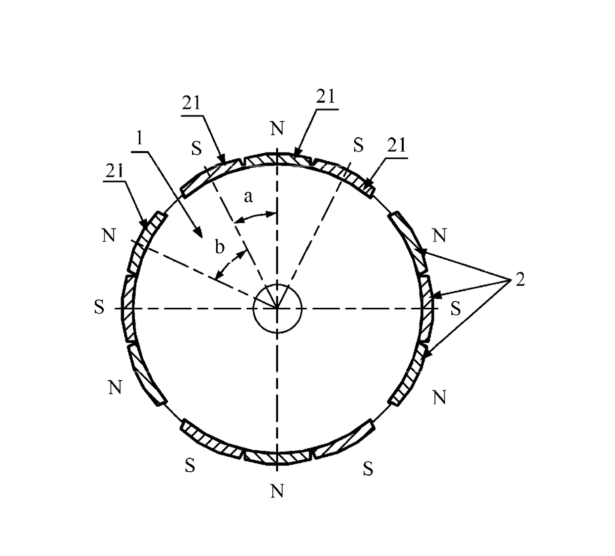
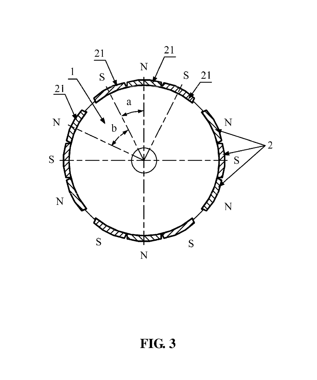
[0029]As shown in FIGS. 3, 4 and 5, a motor of the invention comprises a stator and a rotor. The stator comprises a stator core and a coil winding, and multiple wire receiving grooves are disposed on the stator core. The rotor comprises a rotor core 1 and multiple permanent magnets 21, and the permanent magnets 21 are disposed on side wall of the rotor core 1. A ratio between the number of teeth of the wire receiving grooves and that of the permanent magnets 21 is 3:2. Every three of the permanent magnets 21 lean on each other and form a group, a gap is disposed between adjacent groups 2 of permanent magnets, the groups 2 of permanent magnets are circumferentially distributed, magnetic polarities of the permanent magnet 21 are alternatively distributed in a N phase and a S phase, difference in an electric angle A between centers of polarities of adjacent permanent magnets 21 in one group 2 is between 150 degrees and 170 degrees. Difference in an electric angle B between centers of p...
example 2
[0032]A rotor of this embodiment comprises a rotor core 1 and multiple permanent magnets 21. The permanent magnets 21 are disposed on side wall of the rotor core 1. A ratio between the number of wire receiving grooves and that of the permanent magnets 21 is 3:2. Every two of the permanent magnets 21 lean on each other and form a group, a gap is disposed between adjacent groups 2 of permanent magnets, the groups 2 of permanent magnets are circumferentially distributed, magnetic polarities of the permanent magnet 21 are alternatively distributed in a N phase and a S phase, difference in an electric angle A between centers of polarities of adjacent permanent magnets 21 in one group 2 is between 150 degrees and 170 degrees. Difference in an electric angle B between centers of polarities of adjacent permanent magnets 21 in two adjacent groups 2 is between 190 degrees to 210 degrees. The number of the teeth of the wire receiving groove is 12, and the number of the permanent magnets is 8. ...
PUM
 Abstract
Description
Claims
Application Information
 - R&D
- Intellectual Property
- Life Sciences
- Materials
- Tech Scout
- Unparalleled Data Quality
- Higher Quality Content
- 60% Fewer Hallucinations
Browse by: Latest US Patents, China's latest patents, Technical Efficacy Thesaurus, Application Domain, Technology Topic, Popular Technical Reports.
© 2025 PatSnap. All rights reserved.Legal|Privacy policy|Modern Slavery Act Transparency Statement|Sitemap|About US| Contact US: help@patsnap.com