
Endoscope wiper blade cleaner

a wiper blade and wiper technology, applied in the field of cleaning equipment, can solve the problems of affecting the visualization of the surgical site by condensation on the lens, and achieve the effect of improving the visualization effect of the surgical si

Active Publication Date: 2017-09-19
COVIDIEN LP
View PDF66 Cites 31 Cited by
  • Summary
  • Abstract
  • Description
  • Claims
  • Application Information

AI Technical Summary

Problems solved by technology

The buildup of debris and condensation on the lens impairs visualization of the surgical site, and often necessitates cleaning of the lens.

Method used


Image

  • Endoscope wiper blade cleaner
  • Endoscope wiper blade cleaner
  • Endoscope wiper blade cleaner

Examples


Embodiment Construction

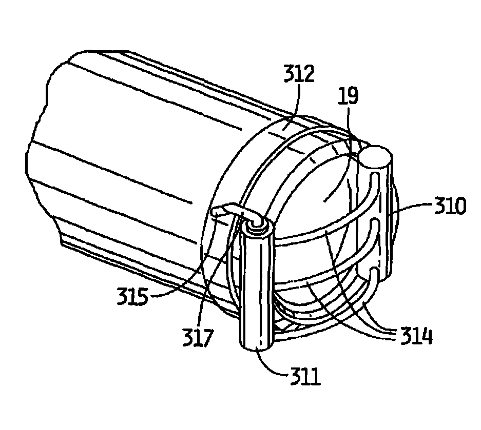
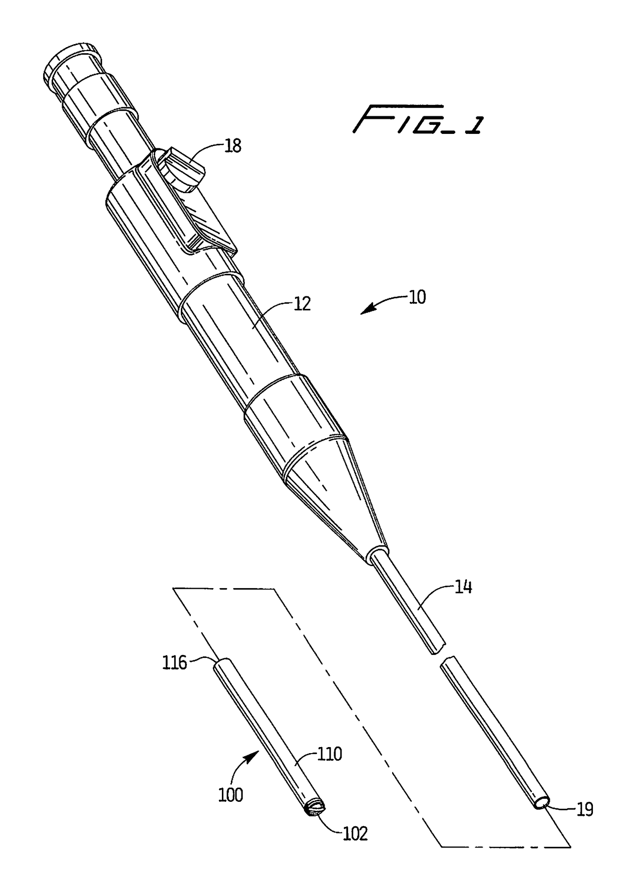
[0026]An endoscope typically includes an endoscope housing or body which can be rigid or flexible, depending on its surgical application. A camera viewfinder, e.g. an eyepiece, is located at a proximal (imaging) end of the scope housing. A lens is provided at the distal end of the scope body.

[0027]In typical use of the endoscope, the viewfinder is adapted to sight images of a surgical field in the patient, e.g. an abdominal cavity, thoracic cavity, etc., as the position of the scope is adjusted to view a particular anatomical structure or structures in the surgical field. The camera is adapted to receive images of the surgical field sighted through the lens and transmit the images to an external monitor that is connected to the camera and on which the images of the surgical field are displayed. That is, a visual display device is operatively connected to the eyepiece to convert the optical signal into a video signal to produce a video image on the monitor (or for storage on select m...


PUM


Abstract

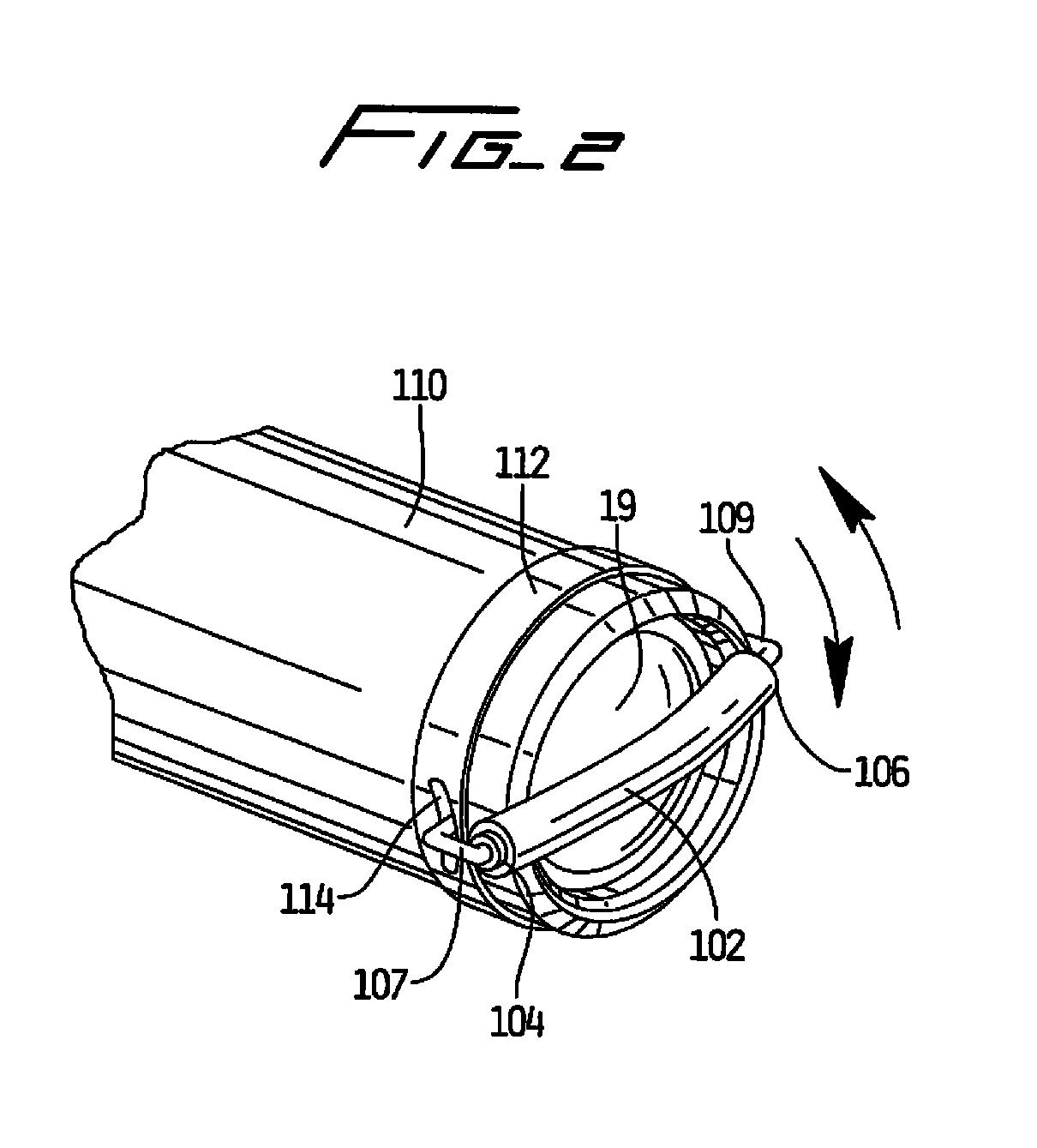
A minimally invasive surgical instrument including a viewing instrument and a wiper mechanism configured and adapted to clean a lens of the viewing instrument. The wiper mechanism includes a wiper that is configured and adapted to contact and translate across a surface of the lens. An actuator moves the wiper across the lens to clean the lens.

Description

[0001]This application claims priority from provisional application Ser. No. 61 / 394,819, filed Oct. 20, 2010, the entire contents of which are incorporated herein by reference.BACKGROUND[0002]Technical Field[0003]The present disclosure relates to a cleaning apparatus configured to remove debris from the lens of a minimally invasive viewing instrument.[0004]Background of Related Art[0005]Minimally invasive surgery has become increasingly popular in recent years. Minimally invasive surgery eliminates the need to cut a large incision in a patient, thereby reducing discomfort, recovery time, and many of the deleterious side effects associated with traditional open surgery. Minimally invasive viewing instruments, e.g., laparoscopes and endoscopes, are optic instruments to facilitate the viewing of internal tissues and / or organs.[0006]Laparoscopic surgery involves the placement of a laparoscope in a small incision in the abdominal wall of a patient, to view the surgical site. Endoscopic s...

Claims


Application Information

Patent Timeline
Patent Type & Authority Patents(United States)
IPC IPC(8): A61B1/00A61B1/12A61B1/04A61B1/313
CPCA61B1/126A61B1/0014A61B1/00087A61B1/00091A61B1/00101A61B1/00135A61B1/3132
Inventor O'PREY, CORMACCLARK, CHARLOTTE ADELEFLEMING, ALISTAIR IAN
Owner COVIDIEN LP
Learn More