
Compressor valve health monitor

a compressor valve and monitor technology, applied in the direction of machines/engines, liquid fuel engines, positive displacement liquid engines, etc., can solve the problems of unable to pinpoint the specific valve responsible for the problem, affecting the efficiency of compressors, etc., to achieve accurate alarm levels, improve the effect of notification and analysis, and rapid reporting

Active Publication Date: 2017-09-12
COMPUTATIONAL SYST
View PDF10 Cites 49 Cited by
  • Summary
  • Abstract
  • Description
  • Claims
  • Application Information

AI Technical Summary

Benefits of technology

Enables precise determination of failing valves, reducing unplanned downtime and maintenance costs by allowing for scheduled replacements and preventing equipment wear due to inefficient operation.

Problems solved by technology

Faulty valves substantially decrease compressor efficiency, among other problems.
While such configurations and techniques are useful locating an operational failure of a general region, such as an entire cylinder, they are unable to pinpoint the specific valves responsible for the problem.
Replacing all valves in a region is costly, and downtime due to unplanned maintenance following a valve failure only adds to this cost.
This low frequency range is not suitable for stress wave analysis and contains enormous normal vibration machinery and process operation and background noise information, all of which may be overwhelming compared to important signal information indicative of valve failure.

Method used


Image

  • Compressor valve health monitor
  • Compressor valve health monitor
  • Compressor valve health monitor

Examples


Embodiment Construction

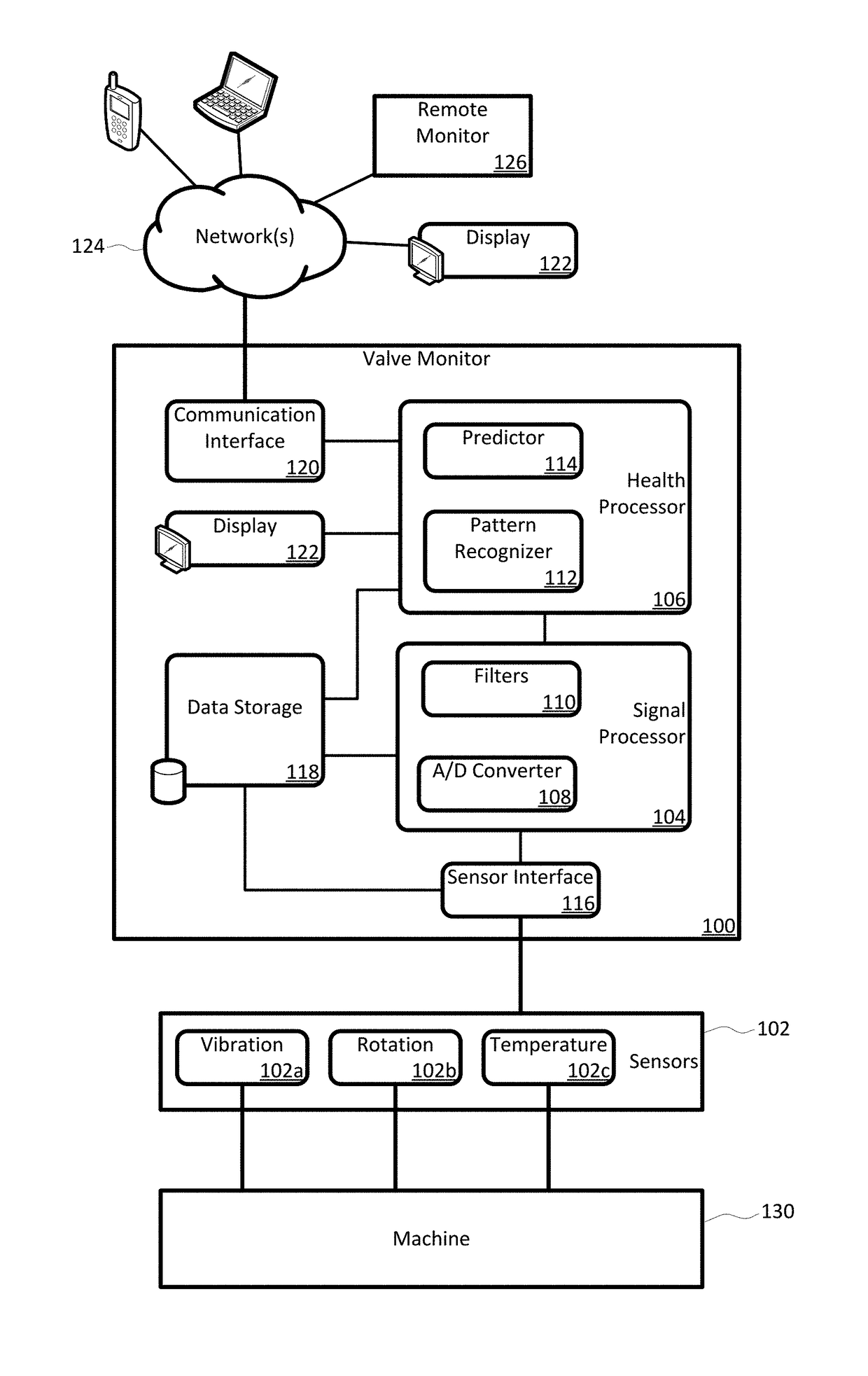
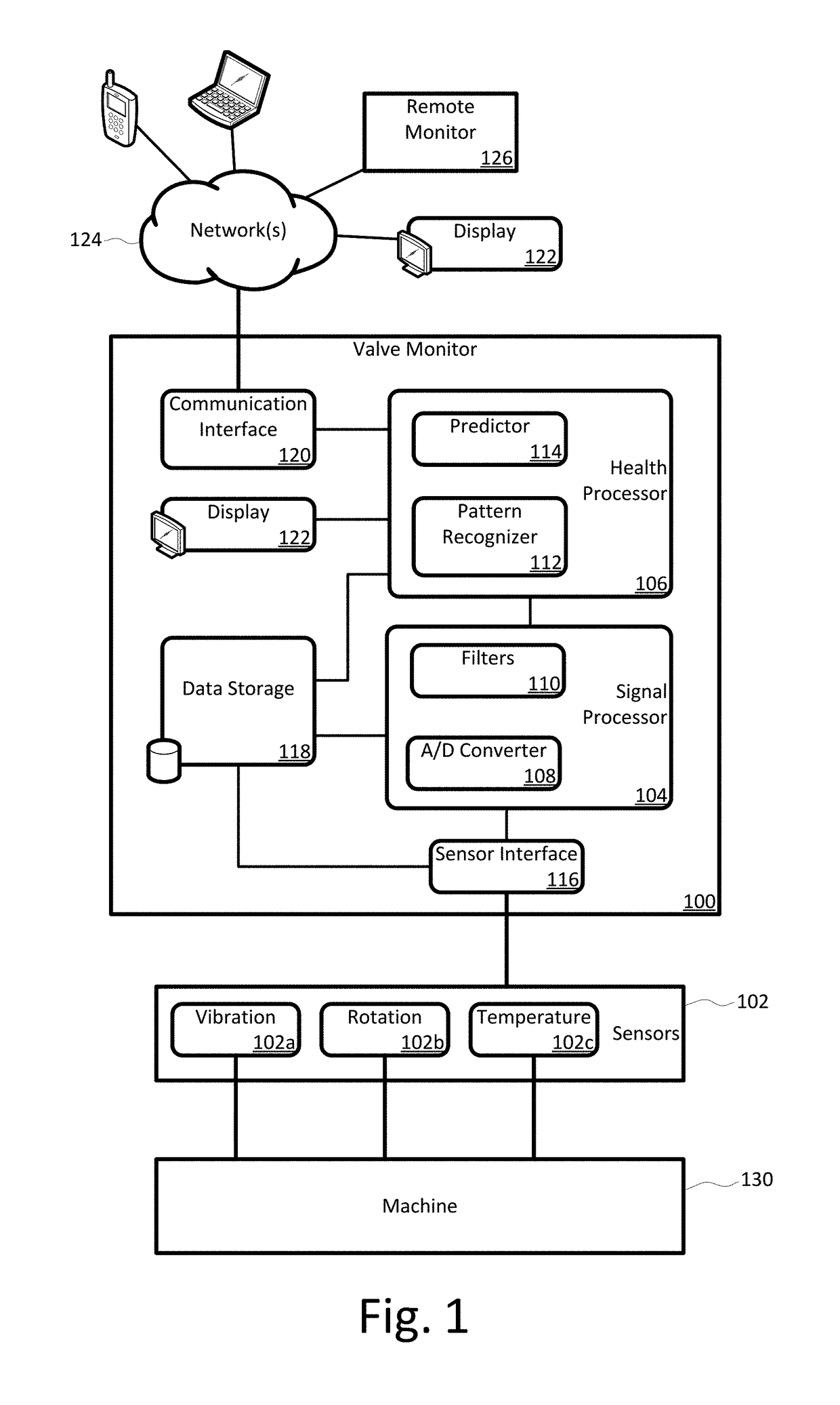
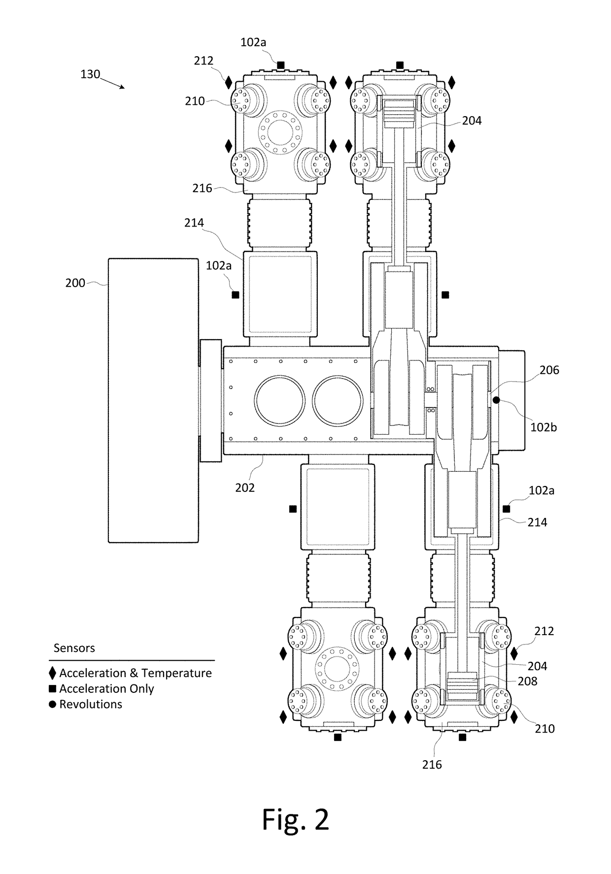
[0037]A rotating machine valve health monitor, or valve monitor, is described herein and illustrated in the accompanying figures. Aspects of the valve monitor include instrumenting each valve of a reciprocating compressor, or other rotating machine, with a sensor capable of detecting at least vibration and instrumenting the crank shaft with a sensor capable of detecting at least rotation. A controller directly monitors the operation and condition of each valve to precisely identify any individual valve exhibiting leakage issues rather than only identifying the region of the leakage. The valve monitor uses a relatively high frequency stress wave analysis technique to provide a good signal-to-noise ratio to identify impact events indicative of leakage. The valve monitor uses circular waveforms of vibration data for individual valves to allow identification of leaking valves by pattern recognition or visual identification. The valve monitor provides ongoing data collection to give warn...


PUM


Abstract

A rotating machine valve health monitor. Aspects of the valve monitor include instrumenting each valve of a reciprocating compressor, or other rotating machine, with a sensor capable of detecting at least vibration and instrumenting the crank shaft with a sensor capable of detecting at least rotation. A controller directly monitors the operation and condition of each valve to precisely identify any individual valve exhibiting leakage issues rather than only identifying the region of the leakage. The valve monitor uses a relatively high frequency stress wave analysis technique to provide a good signal-to-noise ratio to identify impact events indicative of leakage. The valve monitor uses circular waveforms of vibration data for individual valves to identify leakage by pattern recognition or visual identification. The valve monitor provides ongoing data collection to give warning of predicted valve failure and scheduling of preventative maintenance for failing valves.

Description

CROSS-REFERENCE TO RELATED APPLICATIONS[0001]Not Applicable.BACKGROUND[0002]Suction and discharge valves generally present the biggest maintenance concern on reciprocating compressors. Faulty valves substantially decrease compressor efficiency, among other problems. Conventional compressor monitoring systems rely heavily on analysis of pressure-volume (PV) curves to evaluate operation and determine status of suction and discharge valves in large reciprocating compressors. Such conventional compressor monitoring systems also monitor crosshead vibration or utilize portable ultrasonic sensors to evaluate valve health. While such configurations and techniques are useful locating an operational failure of a general region, such as an entire cylinder, they are unable to pinpoint the specific valves responsible for the problem. Replacing all valves in a region is costly, and downtime due to unplanned maintenance following a valve failure only adds to this cost.[0003]More recently, a non-in...

Claims


Application Information

Patent Timeline
Patent Type & Authority Patents(United States)
IPC IPC(8): F04B39/10F04B49/06F04B53/10F04B27/04F04B51/00
CPCF04B51/00F04B27/0451F04B39/10F04B49/065F04B53/10F04B2203/0209F04B2207/70
Inventor BASSETT, TIMOTHY SCOTTHELLER, MATTHEW CARLFORD, TERRY LYNN
Owner COMPUTATIONAL SYST
Learn More