
Portable diagnostic apparatus for testing circuit breakers

a diagnostic apparatus and circuit breaker technology, applied in the field of circuit breakers, can solve the problems of not being able to racked out of the framework, not having built-in diagnostic sensors, and making the diagnosis of the real problem more difficul

Inactive Publication Date: 2017-09-05
EATON INTELLIGENT POWER LTD
View PDF36 Cites 6 Cited by
  • Summary
  • Abstract
  • Description
  • Claims
  • Application Information

AI Technical Summary

Problems solved by technology

On other cases, the circuit breakers are mounted on customized framework, generally called a fixed breaker, and may not be able to racked out of the framework.
These older circuit breakers, unlike many more modern circuit breakers, do not have any built-in diagnostic sensors for monitoring the operation thereof.
Diagnostic testing and repair at such a remote maintenance site often makes the diagnosis of the real problem more difficult, since the circuit breaker will often have to be tested without electrical control power due to the unavailability of a proper fixture such as switchgear enclosure, testing cabinet, etc.
In addition, on-call service Engineers or maintenance staff at the customer's site may face problems understanding the breaker mechanism and may not be able to repair the issue due to lack of knowledge and / or sensor diagnostic data.
Further, the time constrains at maintenance shops due to the cost associated with the downtime or maintenance itself are critical.

Method used


Image

  • Portable diagnostic apparatus for testing circuit breakers
  • Portable diagnostic apparatus for testing circuit breakers
  • Portable diagnostic apparatus for testing circuit breakers

Examples


Embodiment Construction

[0018]Directional phrases used herein, such as, for example, left, right, front, back, top, bottom and derivatives thereof, relate to the orientation of the elements shown in the drawings and are not limiting upon the claims unless expressly recited therein.

[0019]As employed herein, the term “number” shall mean one or an integer greater than one.

[0020]As employed herein, the statement that two or more parts are “coupled” together shall mean that the parts are joined together either directly or joined through one or more intermediate parts.

[0021]As employed herein, the term “time signature” shall mean a visual representation of a number of waveforms each indicating a time sensitive parameter relating to the operation of a circuit breaker or switchgear / cell and / or the data that may be used to represent, render or otherwise generate such a visual representation.

[0022]A circuit breaker has its own working logic, which is implemented electro-mechanically using an interlock mechanism, sep...


PUM


Abstract

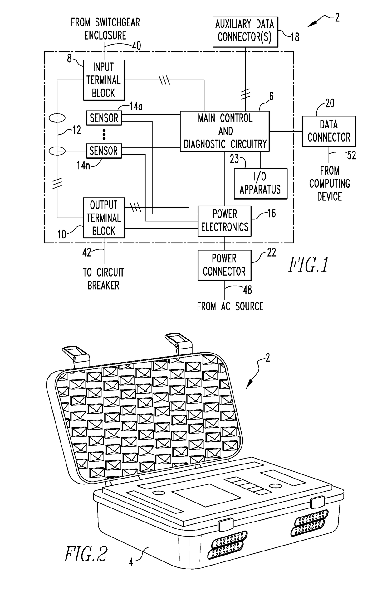
A portable diagnostic apparatus for performing diagnostic testing on a circuit breaker includes a number of sensor devices structured to generate a number of sensed parameter signals relating to operation of the circuit breaker during an operational sequence, a number of auxiliary input connectors structured to receive a number of auxiliary data signals from the circuit breaker, the number of auxiliary data signals relating to and being generated in response to the operation of the circuit breaker during the operational sequence, and control and diagnostic circuitry. The control and diagnostic circuitry is structured to control operation of the portable diagnostic apparatus, receive the number of sensed parameter signals and the number of auxiliary data signals, and generate a time signature based on the number of sensed parameter signals and the number of auxiliary data signals.

Description

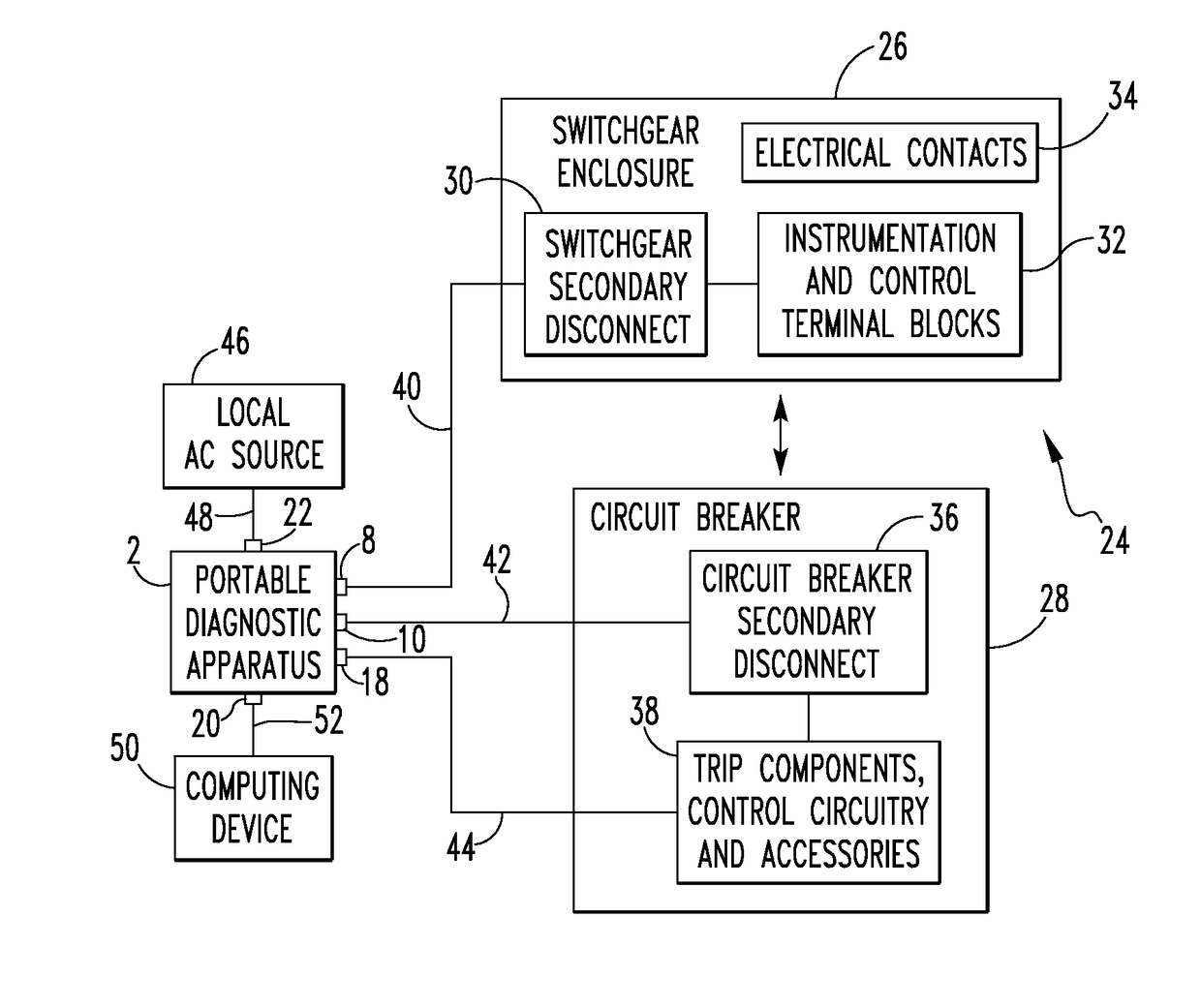
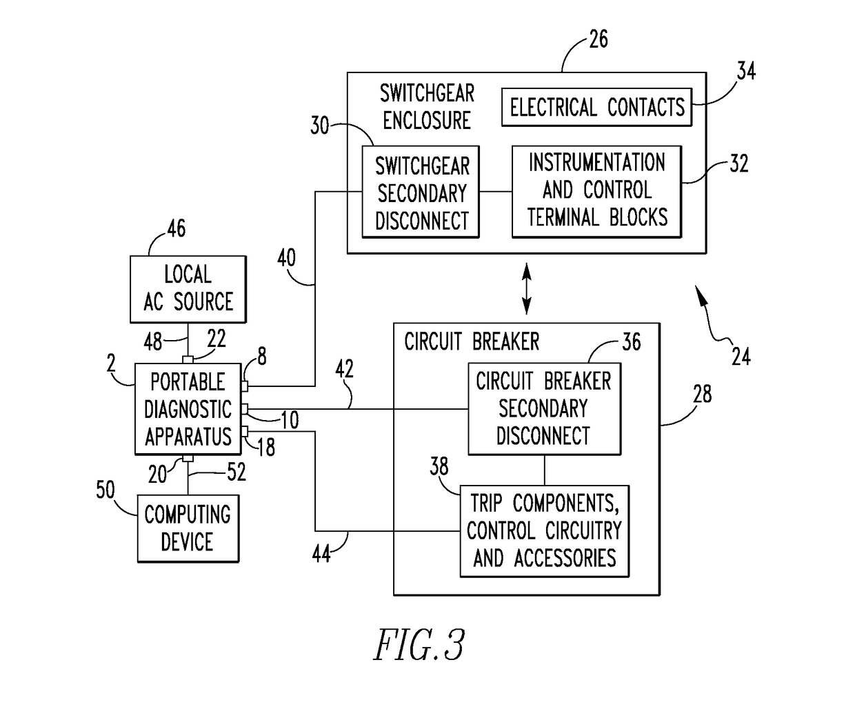
BACKGROUND[0001]Field[0002]The disclosed concept pertains generally to circuit breakers used in power transmission and distribution systems, and, more particularly, to a portable diagnostic apparatus including an onboard diagnostic feature for performing diagnostic testing on circuit breakers, such as, without limitation, low or high voltage power circuit breakers.[0003]Background Information[0004]Electrical power transmission and distribution systems typically utilize a plurality of power circuit breakers which include one or more sets of separable contacts for protecting circuits against overcurrent conditions. In the field, a number of such circuit breakers are generally mounted and housed within a non-conductive housing or enclosure, often referred to as a switchgear enclosure. Power connections for the circuit breakers are generally terminated in the rear of the enclosure, and instrumentation and control terminal blocks for the circuit breakers may either be mounted in the rear...

Claims


Application Information

Patent Timeline
Patent Type & Authority Patents(United States)
IPC IPC(8): G01R31/02G01R31/327G01R27/20G01R31/333H01H1/00
CPCG01R31/3272G01R27/20G01R31/3274G01R31/3278G01R31/3333G01R31/3336H01H1/0015G01R1/04
Inventor ASHTEKAR, KOUSTUBH DNYANDEOBENKE, JAMES JEFFERYHOLLAND, GREG D.
Owner EATON INTELLIGENT POWER LTD
Learn More