
Water-pollutant separation device, water-pollutant separation and filtration device, ornamental fish tank water-pollutant separation and filtration system, and high density cultivation water-pollutant separation, filtration and oxygen aeration system

a technology of water-pollutant separation and filtration device, which is applied in the direction of filtration separation, separation process, settling tank feed/discharge, etc., can solve the problems of reducing the water flow rate and filtration effect, reducing the efficiency of filtration, and reducing the time-consuming work of washing filtration materials, etc., to achieve easy discharging of pollutant and free of disassembly and cleaning

Active Publication Date: 2017-09-05
CHANG JUNBIN
View PDF8 Cites 2 Cited by
  • Summary
  • Abstract
  • Description
  • Claims
  • Application Information

AI Technical Summary

Benefits of technology

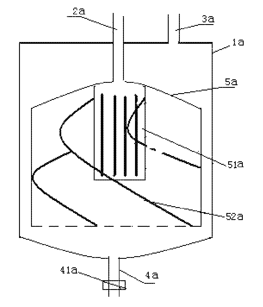
[0004]The object of the present invention is to provide a water-pollutant separation device free of disassembling and cleaning and easy for discharging pollutant, on which a water-pollutant separation and filtration device, an ornamental fish tank water-pollutant separation and filtration system, and a high-density cultivation water-pollutant separation, filtration and oxygen aeration system that are based on.
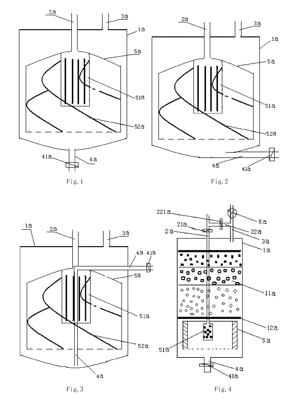
[0005]In order to obtain one or more of these objects, the present invention provides a water-pollutant separation device, comprising a tank, a water inlet pipe and a water outlet pipe respectively communicated with the top of the tank, and a pollutant discharge pipe communicated with the bottom of the tank, wherein, the inner cavity of the tank is provided with a separation structure being in such an inverted-barrel shape that has an upper closing cover, a slightly smaller external dimension than that of the tank, a gap from the bottom of the tank, and a spoiler, which is installed onto the water inlet pipe after which goes through the upper closing cover of the separation structure in the tank, having a sealed lower-end and a plurality of openings or slots on the side-wall to generate subcritical flow to spoil the water flow. The technical scheme presents a water-pollutant separation device before the filtration treatment for fish tank, in which the openings or slots on the side-wall of the spoiler shunt the strong water into flows so that the pollutant in the water can be easily separated and discharged. With less pollutant accumulating in the filtration materials, the water quality can be improved and stable.
[0006]Preferably, the dimensions of the openings or slots on the side-wall of the spoiler gradually decrease from the top to the bottom, thus ensuring the efficiency of the spoiler with a weak water flow.

Problems solved by technology

As time goes on lots of pollutant will accumulate on the filtration materials.
This will reduce the water flow rate and the filtration effect, so washing the filtration materials is a time-consuming work.
However, these schemes remain many disadvantages, for instance, the separation effect for the sedimentation tank or a rotating separation module is very low because of the huge force applied to the particles by the strong water flow.
So a powerful filtration system and a large quantity of fresh water are needed to maintain the water quality with a high construction cost and a low use ratio.

Method used


Image

  • Water-pollutant separation device, water-pollutant separation and filtration device, ornamental fish tank water-pollutant separation and filtration system, and high density cultivation water-pollutant separation, filtration and oxygen aeration system
  • Water-pollutant separation device, water-pollutant separation and filtration device, ornamental fish tank water-pollutant separation and filtration system, and high density cultivation water-pollutant separation, filtration and oxygen aeration system
  • Water-pollutant separation device, water-pollutant separation and filtration device, ornamental fish tank water-pollutant separation and filtration system, and high density cultivation water-pollutant separation, filtration and oxygen aeration system

Examples


third embodiment

[0055]FIG. 2 and FIG. 3 are schematic views of a second and the water-pollutant separation device according to the present invention, which have a similar structure with the embodiment in FIG. 1. The difference is that the pollutant discharge pipe 4a for discharging pollutant at the bottom of the tank 1a is extending along the horizontal direction below the bottom of the tank 1a to reduce the total product height (as shown in FIG. 2), or is extending along the horizontal direction inside the tank 1a (as shown in FIG. 3).

[0056]When the device in a normal working state, the pollutant discharge pipe valve 41a is turned off and dirty water goes into the spoiler 51a through the water inlet pipe 2a inside the separation structure 5a. With the shunting function of the slots, the cycling water loses impact force and becomes smooth, and then starts whirling in the same direction under the function of the spiral leaves 52a, gathering most particles pollutant within a central area of the botto...

second embodiment

[0061]FIG. 5 is a schematic view of the water-pollutant separation and filtration device according to the present invention, which has a similar structure with the embodiment in FIG. 4. The difference is that the pollutant discharge pipe 4a for discharging pollutant at the bottom of the tank 1a is extending along the horizontal direction inside the tank 1a from bottom to top and then stretch out to reduce the total product height. Still, low density filtration materials 52a, such as brushes made into circle plate or the like, are arranged on the inner side-wall of the separation structure 5b to enhance the filtration effect of weak flow.

[0062]FIG. 6 is a schematic view of one embodiment of the ornamental fish tank water-pollutant separation and filtration system according to the present invention. The inner cavity of the tank 1b is divided by clapboard into the bottom-water filtration area on the left side and the upper-water filtration area on the right side communicating with each...


PUM

PropertyMeasurementUnit
widthaaaaaaaaaa
densityaaaaaaaaaa
volumeaaaaaaaaaa

Abstract

The present invention, relating to a water-pollutant separation device, on which a water-pollutant separation and filtration device, an ornamental fish tank water-pollutant separation and filtration system, and a high density cultivation water-pollutant separation, filtration and oxygen aeration system are based on, comprises a tank, a water inlet pipe and a water outlet pipe respectively communicated with the top of the separation tank, and a pollutant discharge pipe disposed at the bottom of the tank; the inner cavity of the tank is provided with a separation structure which is in an inverted barrel shape, having an upper closing cover and slightly smaller external dimensions than that of the tank which provides a gap between the separation structure and the bottom of the tank; a spoiler is installed onto the water inlet pipe after the water inlet pipe passes through the upper closing cover of the separation structure in the tank; the spoiler is sealed at the lower end, and is provided with a plurality of openings or slots on the side wall to generate a subcritical flow to spoil the water flow, the openings or slots being biased in the same direction. In the technical solution, a water-pollutant separation device is preferably added prior to fish tank filtration, and the multiple slots provided on the spoiler are suitable for splitting the flow of relatively large water flow, so that most pollutants in the water can be separated and discharged, thus reducing the accumulation of the pollutants on filtration material, and improving water quality and stability.

Description

FIELD OF THE INVENTION[0001]The present invention relates to a water-pollutant separation device, on which a water-pollutant separation and filtration device, an ornamental fish tank water-pollutant separation and filtration system, and a high-density cultivation water-pollutant separation, filtration and oxygen aeration system are based on.BACKGROUND OF THE INVENTION[0002]In the field of fish farming, the maintenance of water takes more precedence. The water quality determined by the organic content and dissolved oxygen has a great influence on keeping fish. The organic content in the aquatic water comes from the excretions of the fish and the remained fish food, most of which is remained in the form of particles at the bottom of the fishpond.[0003]In the prior art, the mechanism of the filtration system for fish-tank is that internal filtration materials blocks the particles pollutant to purify the water. As time goes on lots of pollutant will accumulate on the filtration material...

Claims


Application Information

Patent Timeline
Patent Type & Authority Patents(United States)
IPC IPC(8): B01D21/00B01D21/24A01K63/04B01D35/02B01D29/56A01K63/00
CPCA01K63/045A01K63/042B01D21/0054B01D21/2405B01D29/56B01D35/02
Inventor CHANG, JUNBIN
Owner CHANG JUNBIN
Learn More