
Turbocharger having a bearing housing

a technology of bearing housing and turbocharger, which is applied in the direction of machines/engines, mechanical equipment, liquid fuel engines, etc., can solve the problems of whirl vibration noise and whirl vibration noise, and achieve the effects of reducing whirl vibration, high thermal conductivity, and reducing whirl vibration

Inactive Publication Date: 2017-08-29
TAIHO INDUSTRIES CO LTD
View PDF19 Cites 0 Cited by
  • Summary
  • Abstract
  • Description
  • Claims
  • Application Information

AI Technical Summary

Benefits of technology

The design effectively reduces whirl vibration by increasing lubricating oil volume and absorbing heat, preventing deformation and damage from high temperatures, while maintaining structural integrity and reducing noise.

Problems solved by technology

However, in the case where the sliding bearing is used in a portion rotating at high speed like the shaft of the turbocharger, since clearances between the bearing housing and the sliding bearing and between the sliding bearing and the shaft are narrow, whirl vibration may occur in the portion.
Further, in the case where the whirl vibration occurs, noise (abnormal sound) caused by the whirl vibration may occur.

Method used


Image

  • Turbocharger having a bearing housing
  • Turbocharger having a bearing housing
  • Turbocharger having a bearing housing

Examples


Embodiment Construction

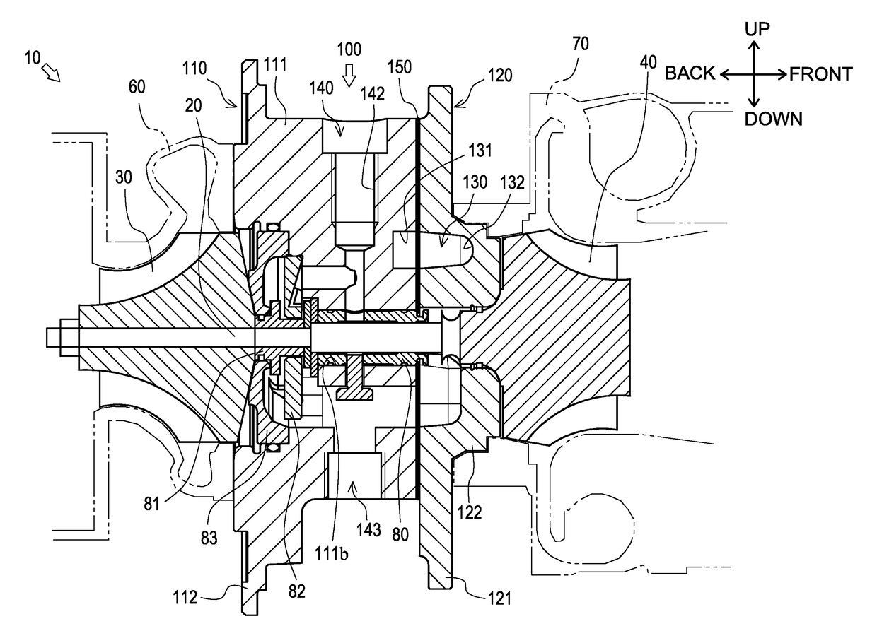
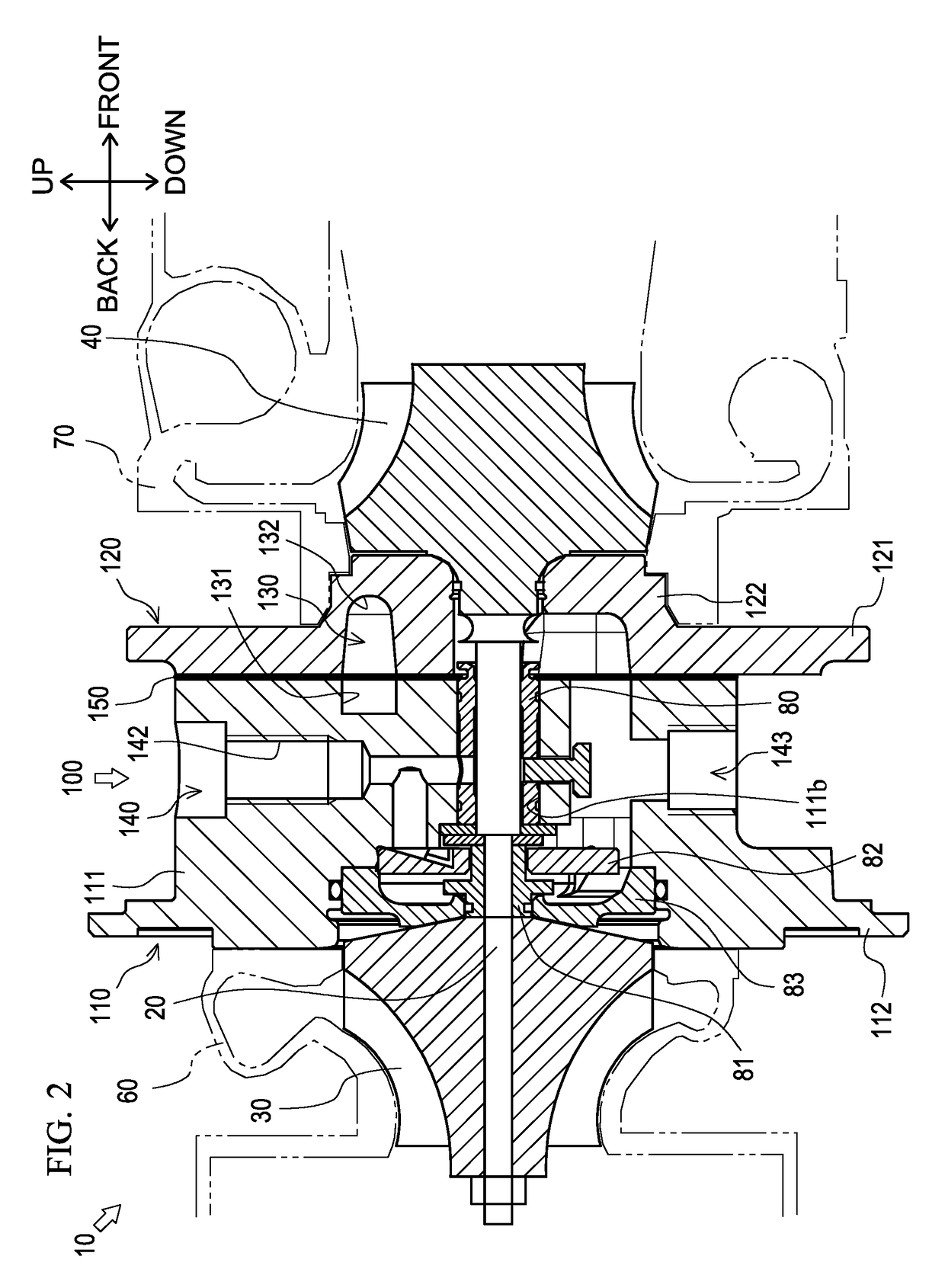
[0038]In the following description, in accordance with arrows shown in the figures, a front-back direction, an up-down direction, and a left-right direction are defined individually.

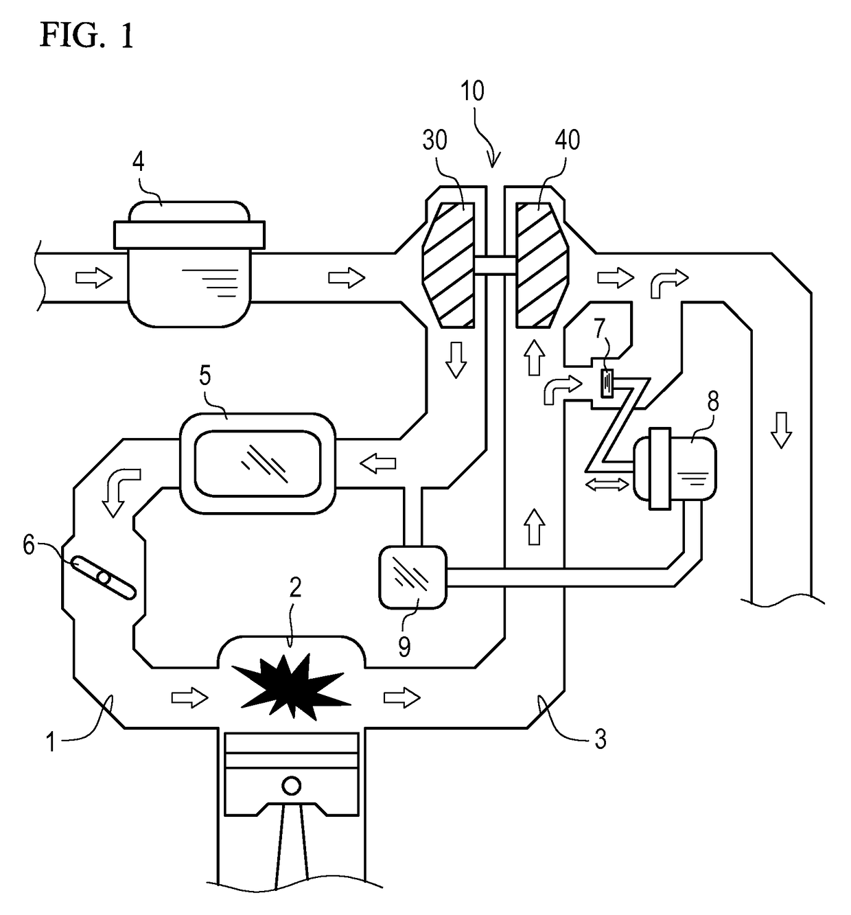
[0039]With reference to FIG. 1, description will be given of an overview of operation for a turbocharger 10 according to one embodiment of the present invention.

[0040]The turbocharger 10 is for feeding compressed air into a cylinder 2 of an engine. The air is supplied to the cylinder 2 via an intake passage 1. The air sequentially passes through an air cleaner 4, the turbocharger 10, an intercooler 5, and a throttle valve 6 which are disposed along the intake passage 1, and then the air is supplied to the cylinder 2. At this time, since a compressor 30 of the turbocharger 10 compresses the air, much more air can be fed into the cylinder 2.

[0041]High-temperature air (exhaust) after burning inside the cylinder 2 is discharged via an exhaust passage 3. At this time, the exhaust rotates a turbine 40 of the t...


PUM

PropertyMeasurementUnit
speedaaaaaaaaaa
temperatureaaaaaaaaaa
inner diameteraaaaaaaaaa

Abstract

There is provided a turbocharger which can reduce whirl vibration. The turbocharger includes a shaft connecting a turbine and a compressor, a bearing housing having a bearing portion turnably supporting the shaft, and a sliding bearing interposed between the shaft and the bearing portion. The bearing portion is formed of an aluminum-based material, the shaft is formed of a steel material, and the sliding bearing is formed of a copper-based material.

Description

TECHNICAL FIELD[0001]The present disclosure relates to a technique of a turbocharger provided in an internal combustion engine.BACKGROUND ART[0002]Conventionally, there has been publicly known a technique of a turbocharger provided in an internal combustion engine. Such a technique of a turbocharger is disclosed, for example, in Japanese Patent Application Laid-Open No. H9-310620.[0003]The turbocharger rotatably supports a shaft, by a bearing housing, connecting a turbine driven by exhaust gas and a compressor for compressing intake air. Further, the turbocharger includes a sliding bearing interposed between the bearing housing and the shaft, and is configured such that the shaft is rotated smoothly.[0004]However, in the case where the sliding bearing is used in a portion rotating at high speed like the shaft of the turbocharger, since clearances between the bearing housing and the sliding bearing and between the sliding bearing and the shaft are narrow, whirl vibration may occur in...

Claims


Application Information

Patent Timeline
Patent Type & Authority Patents(United States)
IPC IPC(8): F04D29/66F04D29/02F04D29/056F01D25/12F01D25/24F01D25/16
CPCF04D29/668F01D25/12F01D25/166F01D25/24F01D25/243F04D29/023F04D29/056F05D2220/40F05D2240/54F05D2260/231F05D2300/10F05D2300/171F05D2300/173
Inventor TAKAMA, KENICHIROKANBARA, SATORUMAKI, KEIJIRONARUSE, RYUJI
Owner TAIHO INDUSTRIES CO LTD
Learn More