
Latch relay

a technology of latching relay and latching plate, which is applied in the field of latching relay, can solve the problems of reducing the operational affecting the performance affecting the operation of the latching plate, so as to maintain the consistency of the conduction performance and cutoff (breaking) performance, reduce the variation of load, and uniform the operation distance of the movable contactor

Active Publication Date: 2017-08-22
LSIS CO LTD
View PDF36 Cites 8 Cited by
  • Summary
  • Abstract
  • Description
  • Claims
  • Application Information

AI Technical Summary

Benefits of technology

The patent describes a latch relay that can maintain consistent performance over time. It achieves this by reducing the amount of force applied to the moving parts, which ensures consistent operation and reliable performance. The relay uses a support member and elastic member between the movable contact and the transmission lever, allowing the contact to make and break smoothly while maintaining stable conduction and breaking performance. The elastic member also acts as a spring to maintain consistent operation performance, increase durability, and reduce variations in product deformation. In summary, this latch relay provides reliable and consistent performance over time.

Problems solved by technology

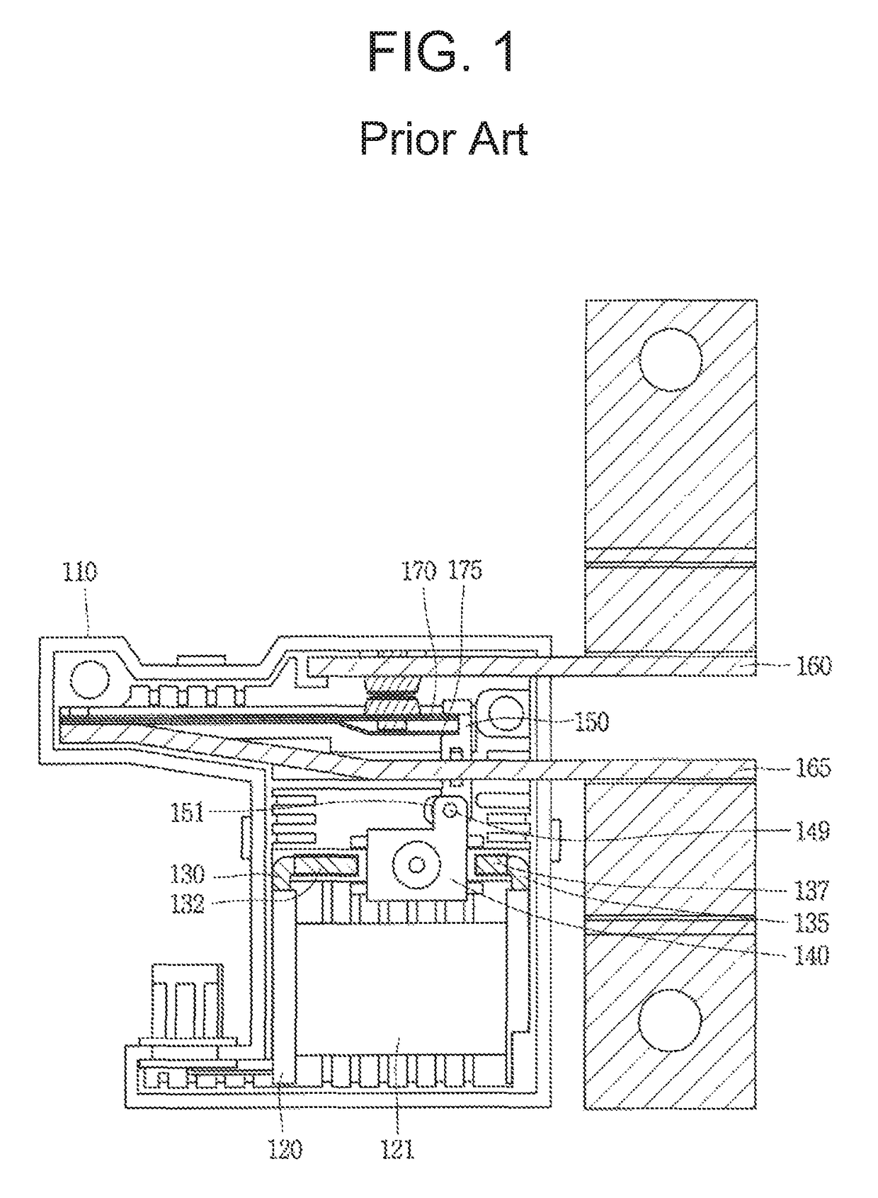
However, in the related art latch relay, as the leaf spring is used for a long period of time, fatigue failure may occur in a material thereof to reduce contact force due to plastic deformation.
Thus, an operational distance of the movable contactor may be reduced to degrade conduction performance or cause defective conduction.
Also, variations occur in operational loads of the leaf spring during ON / OFF operations in terms of material characteristics, causing a problem in that operational characteristics thereof are different in the ON / OFF operations (i.e., when the latch relay is turned on or off).
In addition, the leaf spring has a large load error by products and load variations regarding deformation, resulting in a degradation of consistency by products.

Method used


Image

  • Latch relay
  • Latch relay
  • Latch relay

Examples


Embodiment Construction

[0026]Hereinafter, exemplary embodiments of the present disclosure will be described in detail with reference to the accompanying drawings so that a person skilled in the art to which the present invention pertains to easily implement the invention, but the present invention is not limited thereto.

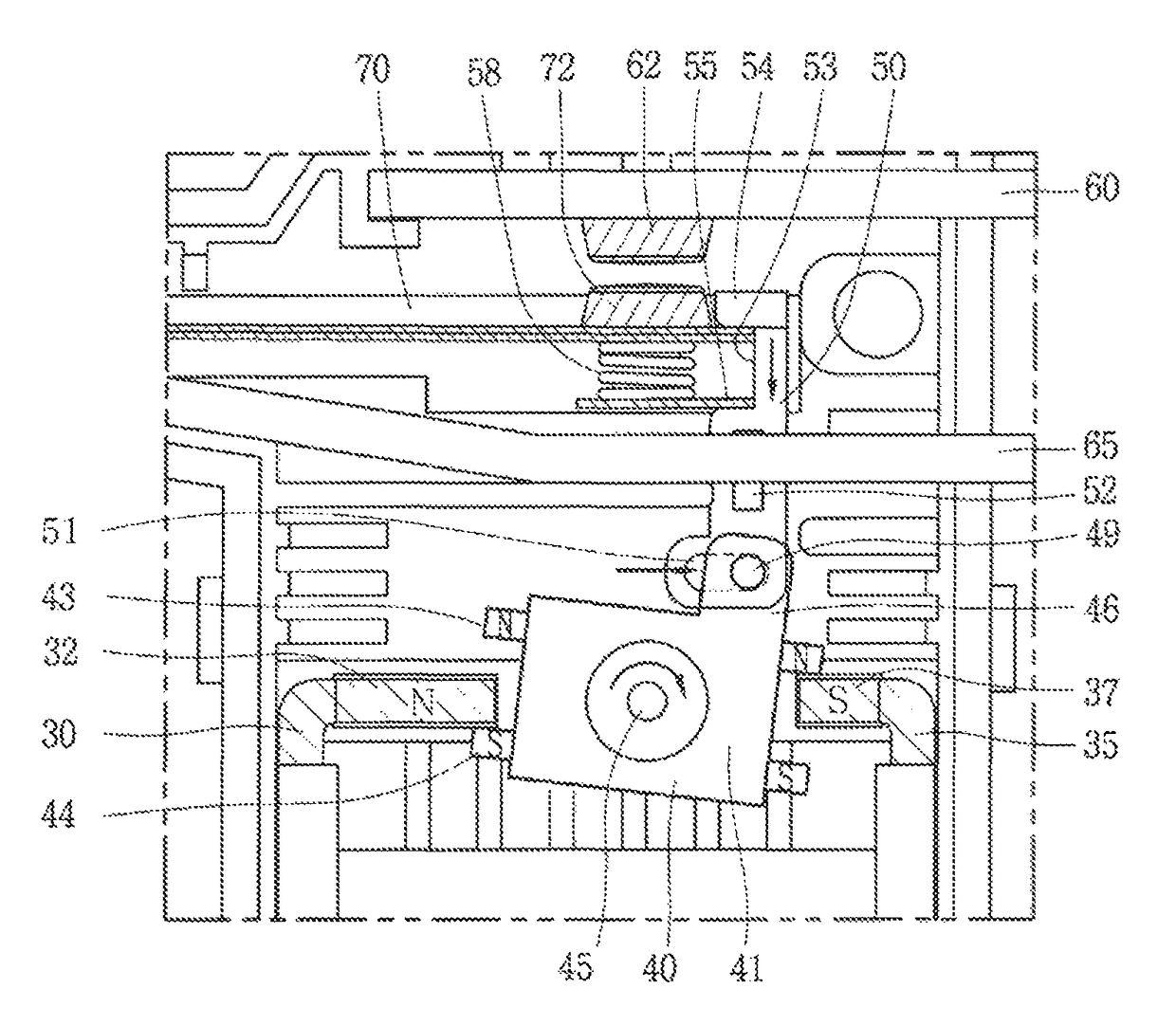
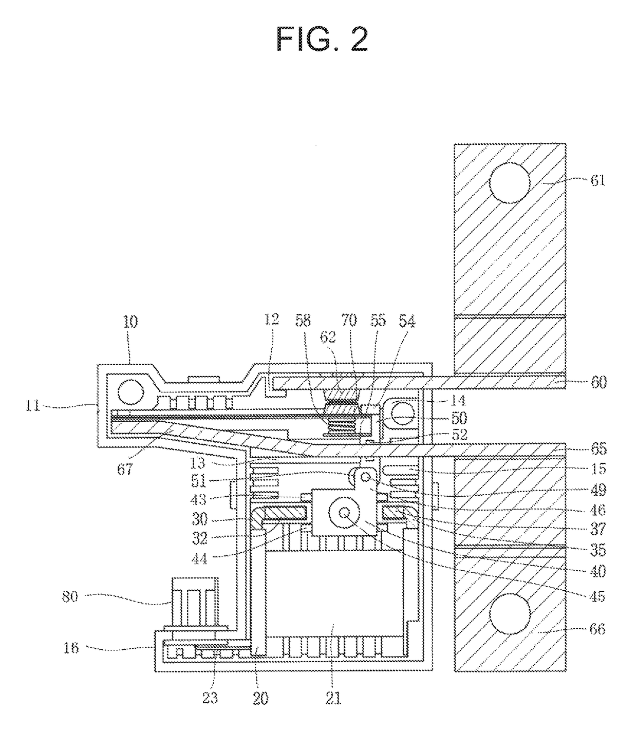
[0027]FIG. 2 is a view illustrating an internal structure of a latch relay according to an embodiment of the present disclosure. FIG. 3 is a partial detailed view of a contact part of FIG. 2. A latch relay according to an embodiment of the present disclosure will be described in detail with reference to the accompanying drawings.

[0028]The latch relay according to an embodiment of the present disclosure includes a frame 10; a bobbin 20 installed in the frame 10 and having a coil 21 wound therearound; first and second yokes 30 and 35 coupled to both sides of the bobbin 20 and provided as magnetic bodies; a rotary mover 40 formed of a magnetic body and rotating in a clockwise direction or in ...


PUM


Abstract

A latch relay includes a frame, a bobbin installed in the frame and having a coil wound therearound, first and second yokes provided as magnetic bodies, a rotary mover rotating in a clockwise direction or in a counterclockwise direction between head portions of the first and second yokes, first and second fixed contactors installed to be spaced apart from one another and parallel to each other within the frame, a movable contactor having one end connected to the second fixed contactor, a transmission lever having one end coupled to one side of the rotary mover to make a vertical movement, a support member fixedly installed on one side of the transmission lever, and an elastic member providing contact force such that the movable contactor is brought into contact with the first fixed contactor or separated from the first fixed contactor, while moving according to a movement of the transmission lever.

Description

CROSS-REFERENCE TO RELATED APPLICATION[0001]Pursuant to 35 U.S.C. §119(a), this application claims the benefit of earlier filing date and right of priority to Korean Patent Application No. 10-2015-0100625, filed on Jul. 15, 2015, the contents of which are all hereby incorporated by reference herein in its entirety.BACKGROUND OF THE INVENTION[0002]1. Field of the Invention[0003]The present disclosure relates to a latch relay and, more particularly, to a latch relay having consistency of performance by reducing a load variation applied to a movable contactor and maintaining a uniform operational distance of the movable contactor.[0004]2. Background of the Invention[0005]In general, a relay or an electromagnetic contactor is a type of an electric circuit switching device transmitting mechanical driving signal and a current signal using a principle of an electromagnet, which is installed in various industrial facilities, machines, and vehicles.[0006]Among relays, in particular, a latch ...

Claims


Application Information

Patent Timeline
Patent Type & Authority Patents(United States)
IPC IPC(8): H01H9/00H01H50/36H01H50/24
CPCH01H50/36H01H50/24H01H2235/01
Inventor CHOI, YEONSOON
Owner LSIS CO LTD
Learn More